UK/VRC-321
Introduction
The UK/VRC-321 is a medium power HF transceiver which was the fixed and mobile HF station for Clansman. It is built in a cast aluminium 1 ATR case and has a companion ATU ("TURF-25W?"), Bandpass Filter ("SURF-25W?") and RTTY modem ("Adapter Telegraph Radio?").

The UK/VRC-321 supports CW, AM and USB from 2 to 30MHz with 100Hz tuning steps. It has two output power levels - low power is 3 to 5 watts and high power is 30 to 50 watts. Most specimens deliver higher power below 10MHz than above 20MHz. The radio has exceptional frequency stability to support two 85-Hz shift AFSK telegraph circuits and has features for remote operation and diversity reception in conjunction with the ATR. The set can be operated standalone or as part of an AFV harness with other Clansman sets. It is rather less sensitive than the UK/PRC-320 - by about 6dB according to the difference in Test Set Condition? settings and seems to have been optimised for selectivity to work well in multi-station co-located sites rather than weak signal performance although this mattered less with the extra power of the 322 available for long paths.
The UK/VRC-321 is all solid state with one motorised tuning element (the selectivity unit) but much less integrated than the RACAL or Plessey components of Clansman, being mostly discrete transistors and simple TTL logic inside.
History
The UK/VRC-321 was manufactured by MEL at Crawley. On its own it replaced the Larkspur C42 and C11/R210 stationas and with a 250W Linear Amplifier and 250W ATU added to form the UK/VRC-322 it replaced the C11 High Power and D11/R234 stations. It was not quite the first SSB radio in British Army service (there was a C11 SSB variant) but, along with the UK/PRC-320 it was the first time that SSB was deployed beyond specialist signals users. Because the Clansman implementation of Radio Teleprinter (RTT, RTTY or RATT) used AFSK it is not compatible with the Larkspur CFS (FSK) implementation and can only interwork with C11 SSB and D11/R234 in that mode.
As with most Clansman sets it was in service from around 1976 to 2008. Serial numbers from the low hundreds to over 2000 have been seen in surplus sets.
In use the sets were mostly vehicle mounted in FFR Landrovers and scouting vehicles which needed medium to long range communications. It is limited by being very non frequency agile (a tuning step of even 1KHz takes 10-15s to complete while the selectivity unit retunes) and is vulnerable to radio direction finding as a result. It has no inherent communication security so it is necessary to encode and decode messages prior to CW, voice or RTTY transmission. This was done with a manual BATCO cipher in the field although I expect more advanced methods could be used for RTTY.
The UK/VRC-321 was replaced by the Harris RF-5800 Falcon 2 in its UK/VRC-328 and UK/VRC-329 mobile installations when Clansman was replaced by Bowman.
Description
Overview
The UK/VRC-321 is a 40 watt transportable HF transceiver in a cast aluminium case of 1 ATR size (a standard aviation package size) which is designed to form a stack with its ATU and Bandpass Filter. All controls and connectors are on the front panel. The frequency is set on a row of rotary switches and the other controls are the power, mode and local/remote switches and the volume control. There is a 28V check button which allows the meter to check the DC supply before the set is switched on. There is a main fuse at top left under which was a 2nd fuse holder originally used for an elapsed time indicator. As this contained hazardous Mercury it was removed and the empty fuse holder is often replaced by a switch in Amateur LSB mods. There are two headset connectors, a harness connector (for connection to a vehicle audio system), a power connector, a control connector and two spring loaded binding posts for D10 cable needed for remote operation with an ATR, RCU or remote handset up to 3 miles away. Unlike most NATO radios that needed an external interface box (or indeed the UK/PRC-320 with its CRL-R? box) the 321 has all of the remote interface built in and nothing is needed at the set end of the wire. A wire stripper is built into the edge of the case just to the left of the audio sockets.
The 321 is designed to fit standard Clansman mounting rails which are bolted to a vehicle or radio table.
The SURF and TURF are designed to fit on metal trays which clamp to the top of the module underneath. Because the SURF is deeper than the TURF the vertical stacking order, from the bottom, is usually Radio then SURF then TURF which is also the electrical connection order.
The SURF is optional and has an insertion loss of 1.5dB in theory although measured loss is much less. It is needed to provide additional selectivity and spurious filtering when the UK/VRC-321 is co-located with other HF stations. A frequency separation of 15% and a physical separation between antennas of 20 metres was recommended for the bare 321 without a SURF.
Summary Data
| Frequency Range | 1.500MHz to 29.9999MHz by 100Hz steps |
| Frequency Accuracy | +/- 0.7ppm |
| Power - High | 30 to 60 W SSB; 15 to 50W AM and CW |
| Power - Low | 2 to 8W |
| Receive Sensitivity | 0.63uV SSB/CW(W) for 6dB S/N;
3.6uV AM 30% mod for 6dB S/N;
0.32uV CW(N) for 6dB S/N |
| Receive Bandwidth | 1st IF (37 or 43MHz): 16KHz
2nd IF (1.748MHz): 2.7 KHz SSB/CW, 6.5KHz AM(1), 200Hz CW(N) (2) |
| DC Input | 28V DC nominal, 20 to 32V allowed |
| Modes | AM, USB, CW |
| TX AF input | 1.4 to 40 mV into 300 Ohms at audio sockets,
20mv remote or harness inputs |
| RX AF output | 2uV CW/SSB 6.3uV AM for 50mW audio into 150 Ohms |
| Supply Current | 1.2 Amps Receive, 5 Amps LP TX, at least 8 Amps HP TX |
| Temperature | -37 to +52 Degrees Centigrade (Operating) |
| Weight | 51lb = 23KG |
| Dimensions HxWxD | 215x230x356 mm = 8.5x9.0x14 inches |
(from technical Handbook EMER H592 Part 1)
(1) Actually -3.25KHz to +2.25KHz so tones above 2.25KHz are 1/2 amplitude on AM
(2) CW(N) IF is centred for a 2KHz CW note
Accessories
The following accessories can be used
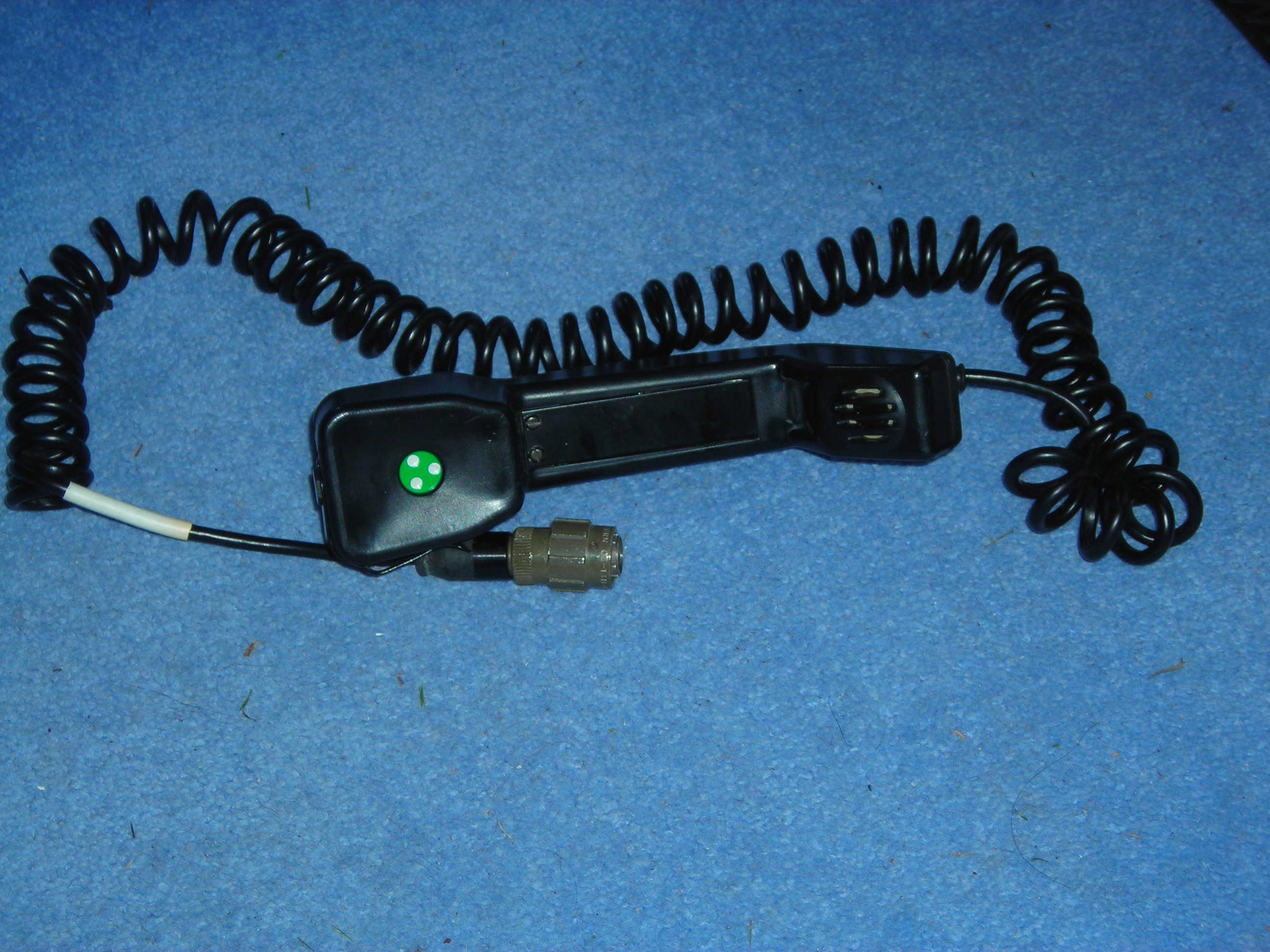
- Standard Clansman Headsets
- Clansman 7 pin and remote handsets
- Clansman Speaker
- Loudspeaker Gun Control
- Clansman Morse Key
- Remote combining unit (RCU?)
- ATR Adapter Telegraph Radio
- BA1020 Automatic ATU (not issued to UK users)
- TURF-25W Manual ATU
- SURF-25W Tuned Bandpass Filter
- T100 Siemens Teleprinter
- 50 Amp Clansman PSU (don't use the "10 Amp" charger PSU)
- MEROD / TDED and DMHD data terminals
This is probably not an exhaustive list
Antennas
The UK/VRC-321 can be directly connected to any 50 ohm antenna. With the standard TURF-25W it can use
- 3 or 4 x 1 metre rods (normally on a Vehicle No.31 base)
- Clansman un-rollable dipole wires
- An end fed antenna with counterpoise
The options are shown on the TURF-25W reference plate:
As with other Clansman ATUs the TURF-25W is designed for electrically short antennas (it is an L circuit with C to ground and series inductance) so optimum verticals and end fed antennas are just short of 1/4 or 3/4 wavelength.
Technical Description
The UK/VRC-321 is a dual conversion superheterodyne transceiver with IFs of 43/37MHz and 1.75MHz implemented mostly with discrete bipolar transistors for analogue functions and small scale (gates and flip-flops) logic from the 54xx series for digital functions. The 54xx series were military temperature range counterparts of the well known 74xx series TTL integrated circuits. The UK/VRC-321 looks like it was designed significantly earlier than the UK/PRC-320 and does not benefit from MSI logic or analogue ICs more complex than op-amps. It still has some mechanically tuned elements although unlike the 320 they are automatically tuned.
This section is an attempt to review the EMER H592 part 1 (available from the VMARS and WS19 archives) in sufficient detail to be useful but not so much detail as to go beyond the fair dealing provisions for criticism, review and quotation in UK copyright law. The EMER itself in the version released under FOIA is dated October 1977 so will be subject to Crown Copyright until October 2027 or October 2152, depending on whether an EMER is considered to have been "published commercially" or not.
Theory of Operation
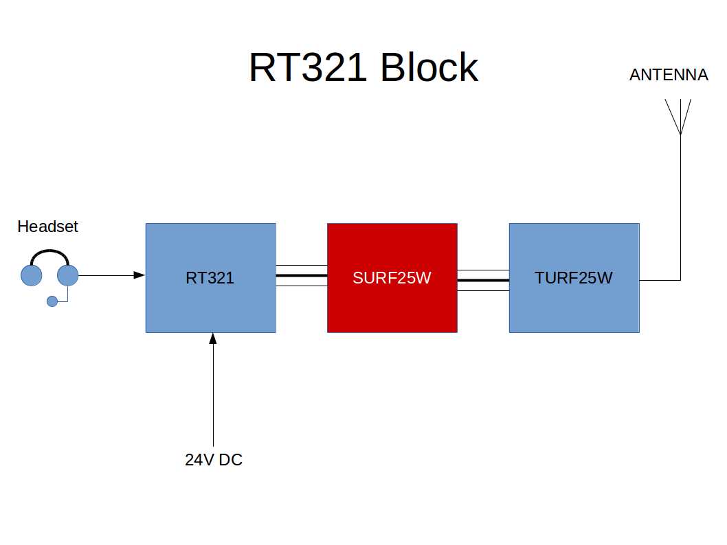
Block Diagram
(Block diagram in preparation and will be uploaded soon )
Radioactive Dial
The UK/VRC-321 used radioactive Tritium lamps (also called beta lights) behind the meter and frequency switches to provide dim lighting at night. The beta lights are unpowered and consist of a glass vial containing a small amount of radioactive tritium gas and a luminous paint activated by the radiation. This was similar to the dial illumination of the Post Office Trimphone and trilux rifle sights of similar vintage.
The Tritium beta lights should not be compared with Radium used in WW2 vintage luminous paint, which will be almost as as active today as when it was made (even if the radiation has worn out the luminous paint so it does not glow as much), and which is solid and persistent in the environment. Radium has a half life of 1600 years, is an alpha emitter with radioactive decay products (Radon gas), and persists in the body replacing Calcium if ingested. Tritium (H3 or radioactive hydrogen) is a gas so will disperse if released, it decays to harmless Helium, and has a short half life of 12 years. Tritium is a beta emitter and the radiation is unlikely to penetrate the glass and certainly very unlikely to penetrate the cast aluminium case. The only possible risk is if the tritium vials are broken in an unventilated confined space. In any case, Tritium has a half life of only 12 years and the radios, being made between 1976 and the early 1980s are now at least 2 and maybe 3 half-lives old, so the residual radioactivity is no more than 1/4 and probably no more than 1/8 of the strength at manufacture.
I can't see any sign of illumination on my 321 at all (I remember dim light on my first one in 2007). I have had partial success getting them to glow with an UV LED light but the angle at which it needs to enter the dials is such that it would need to be mounted on my head to do much good. I suspect replacement of the beta lights with green LEDs or an internal UV LED to illuminate the vials might work better.
Connectors
1SK1 & 1SK2 AUDIO
(7 Pin 12mm Pattern 104 female)
| A | Microphone + |
| B | Microphone - |
| C | +18 to 24V supply from radio to accessories |
| D | Left Headphone |
| E | Headphone and PTT ground |
| F | PTT |
| G | Right Headphone |
A is under the wide keyway and order is ABCDEF anticlockwise looking into the radio, with G in the centre
The headset circuit diagrams show a 2-pole switch - one set of contacts connects PTT pin F to Ground pin E when closed (as does the morse key) and the other set of contacts isolates the microphone pins A and B - this is necessary because the headgear sockets are connected inside the radio and it is better to only hear the microphone of the headset/handset whose PTT was pressed.
1SK3 RF
(BNC 50 Ohm)
This has DC on the centre pin to drive the "reverse power" meter in the TURF. There is a series resistor so short circuits are not harmful. Note that the reverse power sensor is in the radio but the meter is in the TURF ATU.
1SK4 CONTROL
(12 pin Harness Socket)
| A | Input | Tuning indication - when TURF in TUNE mode. Inhibits TX unless radio is in TUNE mode |
| B | Input | External ALC 0-10V reduces TX level |
| C | Output | TX Indication
TX: 2K to ground
RX:100K to ground |
| D | Output | MODE Indication: CW: 2K to Ground
SSB/AM: 100K to ground |
| E | IN/OUT | AGC LINE: Monitor on high z meter or apply 15-30V in to override internal AGC |
| H | Output | RETUNE: When dial changes resistance to earth drops to 2K for 1/2 second |
| K | Input | SELECTIVITY TEST: Ground to disable selectivity unit and RTT power reduction |
| L | Input | TX INHIBIT: Ground to disable TX and get unready tone |
| P | EARTH | Ground - connected to chassis |
| S | Output | PA Power supply volts - +28V on LP, +33V on HP |
1PL1 DC Power
(2 pin 12mm Pattern 104 male)
If correctly fitted the wide keyway is at top and pin A is to the right, looking into the connector.
1PL2 Harness
(7 pin 12mm Pattern 104 male)
| A | Mic + /17V (also remote terminal +) |
| B | Mic - /0V (also remote terminal -) |
| C | Earth |
| D | Phone + |
| E | Phone - |
| F | Not Used |
| G | Earth |
This is meant to be connected to one of the "Radio" sockets on an IB2 or IB3 harness box. Internally it shares circuitry with the remote connectors and the PTT operates by detecting an impedance below 1200 ohms across the microphone terminals (a current of 15mA is needed to operate the PTT).
Synthesizer
The UK/VRC-321 synthesizer is implemented in two parts which physically form modules 7 and 8. Module 7 provides the 1st local oscillator and tunes in steps of 10KHz either 43 or 37MHz above the dial frequency. 43MHz is used for dial frequencies below 7MHz, between 9 and 10 MHz, between 12 and 14 MHz, and between 13 and 19MHz. The IF to be used is determined by extra tracks on the MHz switch. The reason there are alternative 1st IF frequencies is to avoid harmonics of the dial frequency being in the 1st IF pass band. This module also provides a fixed 1.75MHz "3rd LO" carrier used for the modulator and demodulator at 2nd IF frequency. This is the carrier replaced with a 1.7468MHz source in order to get LSB.
Module 8 provides the 2nd local oscillator and tunes in 25Hz steps controlled by the 100Hz and 1KHz switches. The oscillator actually has two VCXOs at 8.81 and 10.31 MHz tuned in 25Hz steps that are multiplied by 4 to work with the 37 and 43MHz first IFs. The module 8 output is mixed with the 1st IF to produce the fixed 2nd IF of 1.748MHz (centre of passband) on received, and mixed with the modulated signal centred on 1.748MHz to get to the 2nd IF on transmit. Note that because the 2nd LO is above the 2ndIF there is a sideband inversion so LSB at 1.748MHz ends up as USB at the antenna. Module 8 also provides the chopper frequency for the PSU which is offset to avoid harmonics falling in the receive passband. The module 8 output is "sidestepped" by +2KHz for SSB and CW to place the dial frequency at the centre of the IF passband (this is different from amateur practice where the dial frequency would be the carrier). In AM the sidestep is not used.
Receive Path
The antenna frequency signal is amplified, filtered by the selectivity unit and mixed with the module 7 synthesized output to get the 43 or 37MHz first IF which is filtered to remove image frequencies before being mixed with the module 8 synthesized output to get to 1.748MHz where the mode-specific IF filtering and demodulation occurs. A product detector is used for CW and SSB, while an envelope detector is used for AM. The audio is then amplified to drive the headphone and remote/harness outputs.
Note that the 1st IF is tunable over a 10KHz range (The demodulator uses a 1.75MHz CIO at the upper end of the 1.748MHz IF passband which is replaced by 1.7468MHz for LSB.
AGC is based on the demodulated signal (SSB and CW) or the 2nd IF amplifier output level (AM) and gain is controlled at four points in the receive chain. Gain is reduced first in the IF and then in the RF stages. A total AGC range of 110dB is available.
Transmit Path
The remote, harness and headset inputs are amplified by a VOGAD to get the correct level and peak clipped to improve modulation depth before being used to drive the high level Cowan Modulator where it is mixed with a 1.75MHz "3rd LO" carrier derived from a TTL level output of module 7. SSB is generated by the filter method, the filter passband being below the carrier from 1.497 to 1.4997 MHz due to sideband inversion (an audio passband of 2.7KHz from 0.3 to 3.0KHz). CW is generated by substituting audio with a 2KHz tone in the SSB modulator. AM modulation is essentially the same as SSB but the AM filter is used allowing both sidebands and the carrier to reach the IF stages. The 1.748MHz / 1.75MHz filtered 2nd IF signal is amplified and mixed with the output of module 8 to get the 1st IF at 37 or 43MHz. The 37 or 43MHz 2nd IF is then mixed with the 1st LO from module 7 to get to the transmit frequency, filtered by the selectivity unit and amplified to 5 or 45 watts by the RF PA stage after which it reaches the antenna via an SWR bridge and harmonic filter.
The RF PA is described below. The harmonic filter comprises two parts - a permanent 30MHz low pass filter and a switched filter added to the TX path by relays for dial settings below 13MHz.
There are a number of protective circuits
- Excessive PA current will trip the PSU
- The ALC is linked to PSU and PA temperature sensors and will reduce power if temperature reaches 85 degrees
- An "RTTY detector" reduces the transmit gain if constant modulation is detected in SSB mode, reducing power to around 25 watts.
- An excess antenna current detector
The ALC is used to control the transmitter output when driving the 250W amplifier as part of a UK/VRC-322 station and to set low power mode. The output power can be adjusted by feeding an ALC voltage through the control socket. The PSU measures the PA current and enforces a limit of 3 amps by means of an input to the ALC circuit. If this fails to limit the trip circuit will operate and can only be reset by powering off the radio.
Side tone is transferred from the TX to the RX path at the 2nd IF so it is not true transmit side tone but a "side tone gate" ensures that it is only audible if an RF output is detected.
Unlike the UK/PRC-320 the UK/VRC-321 microphone inputs from each headset socket and the remote/harness input are individually selected by FET switches according to which PTT is pressed. In CW mode the key controls the 2KHz tone directly but the PTT has an 0.5 second hang time so the set stays in transmit mode between characters. This corresponds to semi-break in operation of an amateur transceiver. It also allows the PTT to be used for keying when tuning without a morse key or in an emergency to send a few characters of CW.
RF PA Stage
CAUTION: The PA transistors have beryllia ceramic cases. Beryllia dust is highly toxic and care must be taken to not release any by cutting scratching or breaking them.
The PA input stage is a single ended 2 stage amplifier formed of a BFW16 then 2 x BLY33 in parallel in class A .
The PA driver stage is a pair of VX6537A NPN transistors transformer coupled in class AB push-pull - you can buy them for £48 (!) from www.thexmod.com but I have never found a data sheet or equivalent.
The final PA was a pair of TRW PT6748 NPN transistors transformer coupled in class AB push-pull - it appears that later replacement modules had the SGS-Thomson SD1733/TH513 - another possible equivalent is the ASI HF30-28S
Looking at the PA Circuit the BLY33 is rated 5W and Class A is 25% efficient at best so allowing for 2:1 or better safety margins I expect the pre-driver gives around a watt into the driver. The final PA pair is capable of a gain of 14dB (mid 20s) to 75W output at 50V DC supply according to the Thompson SD1733/TH513 transistor data sheet - but probably less than that at 28V rather than 50V - so the driver must be primarily an impedance transformation stage with a gain of 2 or 3.
If you do open the set because of PA concerns you could check that the PA input is clean at the coax from 3SK4 to the PA input 1dSK1 with an oscilloscope - at that point it is supposed to be a sinewave of 3V into 50 ohm. A common PA fault is failures of the BF113 bias transistors associated with the PA and driver transistors (which usually leads to a PSU trip). These seem to have been chosen because the can has a separate ground lead independent of the collector rather than for RF performance.
Power Supply
The Power supply is fed via a 10A cartridge fuse. There is a spare fuse under a smaller cap to its right.
The Elapsed Time Indicator immediately under the main fuse was fed from the 5V supply via a 470K resistor and the electrochemical ETI drew 11uA when the radio was switched on resulting in end to end colour change after 1000 hours. Because the ETI contained Mercury it was removed at some point for health and safety reasons. If you find one in a set (it will be the same size as a 10A fuse but will have a red case and a scale of 0 to 1000 in steps of 50) it should be disposed of as toxic waste.
The 321 PSU is fully described at EMER H592 pt 1 page 80 para 225 and the block diagram following. The PSU is fully isolated (so the + and – inputs are independent of ground and the set can be safely used in positive earth vehicles). The input is regulated to 15-17V and chopped to drive the transformer. There is a feedback loop to maintain a constant output from the chopper stage although the output is increased in high power TX mode. The chopper & transformer is actually described as an inverter in some paragraphs of the EMER and the block diagram. The transformer output at 28V (RX or low power TX) or 33V (in high power TX) is rectified and regulated in independent supplies giving
- +5V
- +3V
- -6V
- +33V or +28V depends on TX/RX – non critical supplies
- +12V
- +30V or +25V depends on TX/RX – PA supply
Most outputs are series regulated but the main +12V is switch mode for efficiency reasons. The chopper is synchronised to a synthesiser output at around 25KHz but will free run at 23KHz if synchronisation fails (useful for diagnostics ?). Note that the PSU is integrated with the RF PA protection circuits so an RF problem can cause a PSU trip.
The mean ALC uses the PSU to measure the PA current and sends an ALC control voltage to reduce PA gain as the current reaches 3A. The PSU will trip under the following circumstances:
- Short circuit of any output
- PA current exceeds 3A despite the best efforts of the ALC
- Output voltage high due to regulator failure
- DC input below 20V or above 40V
Remote Operation
The remote terminals are connected in parallel with the harness connector A and B pins. The radio provides a 17V supply on the harness pins and monitors the current to respond to remote controls; the audio transmit and receive circuits are transformer coupled. If the current is
| Less than 4mA | The set will be in receive mode and audio will be sent to the remote |
| 4 to 8mA | The set will be in transmit mode and will be modulated by audio from the remote |
| More than 15mA | The call tone will be heard at the set |
The current is limited to 30mA to avoid damage from short circuits. If the remote switch is set to CALL (a spring loaded momentary position) then a transformer is connected across the remote lines driven by a 2KHz tone so the tone is sent to the remote lines and a DC short circuit is seen by the remote. The former is heard by remote handsets and the latter alerts a remote receiver operator. Tone will also be heard at the local end if the + and - wires are crossed.
The Selector Unit
The selector unit is an electromechanically tuned band pass filter between the RF stages and the 1st mixer. The tuning is in two parts
- a 1MHz band selection driven by tracks on the MHz tuning switch and logic circuits which control a LEDEX stepper - this accounts for most of the noise when retuning
- continuously variable coil tuning within each band controlled by a motor
The selector is triggered when there is a change to any frequency switch except 100Hz, or the set is switched on. The LEDEX first sets the band to one of 8 possibilities decoded from tracks on the MHz switch. The coil is then driven to maximum inductance and the transmitter keyed into an internal dummy load (the antenna is grounded and most of the PA is turned off). The motor is then reversed so it reduces the inductance until a preset low insertion loss is reached. The motor stops after a short delay intended to allow the passband to be centred on the carrier.
Leighton GW3FSP has published a step by step guide to selector replacement at the TCRU Blog.
Servicing
Opening the Case
Opening the case of the UK/VRC-321 is time consuming but not really difficult
- First remove the 8 allen screws round the edges of the front panel
- Then remove the bolts (strictly, screw in plugs) on the top, bottom and rear of the case
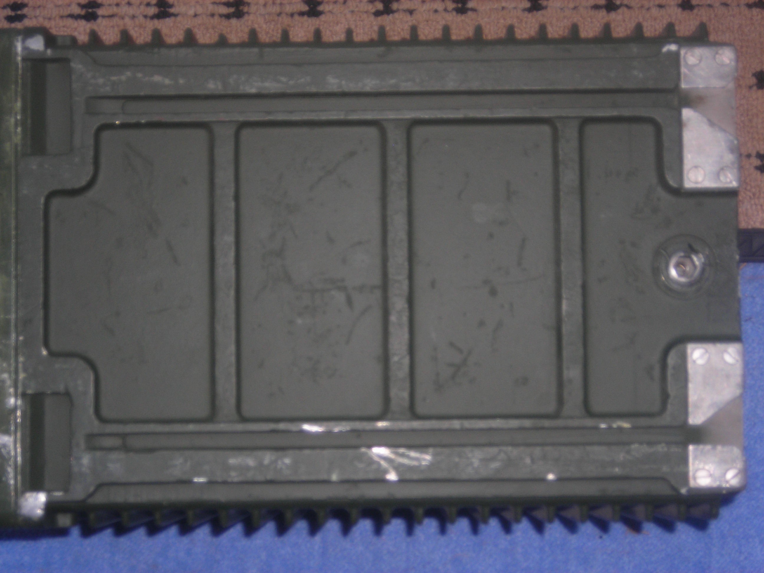
- Some directly contact modules inside for heat transfer,
- others cover an internal allen screw
These do not need to come all the way out but should be loosened 3 or 4 turns
- Set the radio on the floor with the front panel upwards and lift the chassis out using the carrying handle
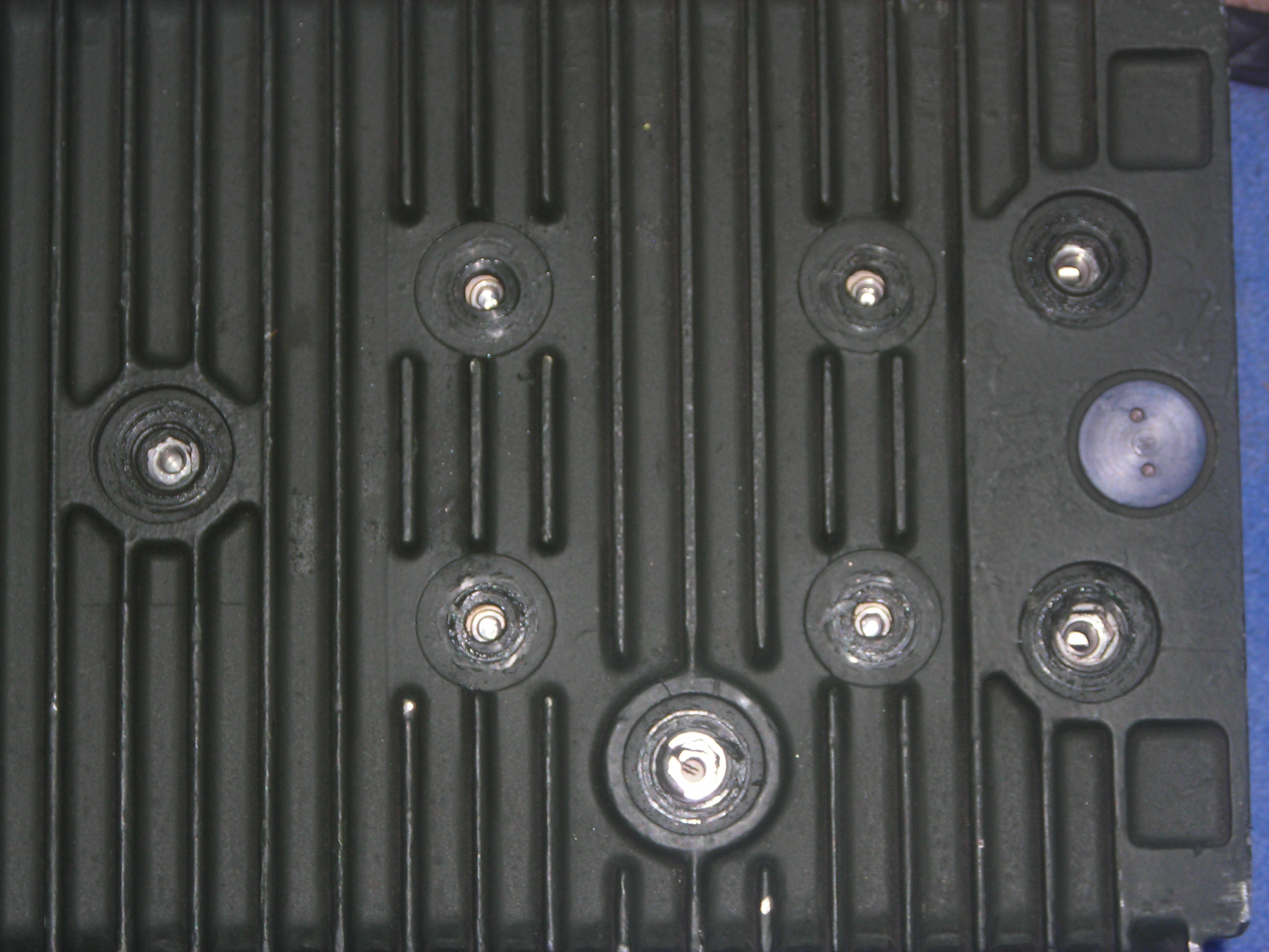
Construction
The UK/VRC-321 is built as a number of modules wrapped around rectangular frame with the front panel at one end.
Each module is connected to a wiring harness for audio, power and control by a solder tag strip and RG-174 miniature coax with SMB push-on connectors for RF. The Tag strip is in two halves which can be unsoldered - heat and desolder (with braid or a pump) each joint in turn and then pull the wire back through the black plastic block to disconnect electrically and mechanically. The black part is part of the cable harness and comes away from the module as a sub-assembly once all the module connections are unsoldered.
The front panel is hinged at the bottom and secured by two bolts at the top. When folded down it gives access to the RF PA module and the "Miscellaneous Functions" board mounted to the front panel.
Interestingly this PA board has TRW PT9007 PA transistors which differs from the circuit diagram !
Modifications
Fast Tuning
(Suppressing the bleeps for small frequency steps)
The 12 pin control connector intended for the 322 amplifier and the automatic test equipment has a pin (pin K) which disables the automatic retuning of the selectivity unit. If this pin is grounded to Pin P then tuning 1KHz or 10KHz steps only takes the synthesizer re-lock time and the set will manage one or two unready bleeps rather than 15 or 20 before it is on the new frequency. I use a 12 pin harness plug with a wire link between pins K and P which I connect to my 321 after tuning to the required band.
LSB Conversion
The theory of conversion is described in detail at my LSB page and a photographic method of the approach has been published by GW3FSP using the G4IQE/G3TPJ board.
2KHz Sidestep removal
The 321 follows the military practice of using the centre of the occupied bandwidth as the dial frequency which means an offset of 2KHz in SSB mode. A mod by GW3FSP is documented at the Clansman Radio User Blog.
Operating
Preparation
The UK/VRC-321, SURF, TURF and antenna should be connected thus:
BNC patch leads should be used between the 321 antenna socket and the SURF input, and between the SURF output and the TURF. If the SURF is not used then the 321 antenna socket is connected directly to the TURF input. To prepare for use:
- Assemble the 321, SURF and TURF in a stack using the mounting rails, trays and clamps
- Fit earth straps or thick earth cables between the earth terminals of the 321, SURF and TURF
- Connect an antenna to the TURF output (either coax to the front panel C-type or a wire to the rear centre terminal)
- If necessary for the antenna connect an RF ground or counterpoise to one of the earth connectors on the back of the TURF
- Connect a Clansman power lead from the 28V input to a suitable 24 to 28V supply
- Press the "28V check" button to ensure that the meter moves to the white central section of the scale, before switching on.
- Connect a headset or handset so you can hear any warning tones
- Remove any shorting link between pins K and P of the control connector so the selector will tune
- Preset the frequency switches to the intended band
- Set the volume control to half way - arrow about at the wide end of the tapered scale
- Set the mode to CW
- Set the remote switch to Local
- If using the TURF and/or SURF switch to TUNE, otherwise switch to low power
- if using the SURF
- Set the SURF range switch to the band in use and the SURF mode switch to "TUNE"
- Key the radio and tune the SURF for maximum meter reading on the radio
- Move the SURF mode switch to "Operate and Lock"
- If using the TURF,
- Unlock the TURF
- Preset the TURF controls to the expected positions for the antenna and band according to the tuning chart
- Key the transmitter and adjust the TURF "TUNE" and "MATCH" controls for best match (maximum reading on both meters)
- Lock the TURF
- If using an external automatic ATU other than the MEL BA1020 then key the radio on low power and wait until the radio meter peaks to indicate that the tuning is successfully completed
- If using an external manual ATU and SWR meter key the radio on low power CW and adjust for best match / lowest SWR which should also be close to the highest reading on the radio's meter
The radio is now ready for use. Switch to the mode and power level of your choice and enjoy the radio.
Controls
The UK/VRC-321 has a continuously variable volume control and three rotary switches in addition to the frequency setting switches. The switches are
Power
This has four positions
- OFF - all power is off. The "28V check" button can still be used to check the DC input.
- LP - Low Power - typically 3 to 5 watts
- HP - High Power - typically 35 to 45 watts
- TUNE - used in conjunction with SURF and TURF; the radio will bleep but can be keyed at low power
Mode
This has four positions
- A.M. - Amplitude Modulation (full carrier on dial frequency, full upper and truncated lower sideband)
- C.W.(W) - Semi Break In Morse Code centred on dial frequency, 3KHz receive bandwidth
- S.S.B - Upper Sideband SSB - 300Hz to 3KHz audio bandwidth, centred on dial frequency
(so dial is 2KHz above carrier which is normally quoted in amateur radio)
- C.W.(N) - Semi Break In Morse Code centred on dial frequency, 200Hz receive bandwidth
Remote
This has five positions
- LOCAL - Normal operating position. Remote can hear but not transmit
- RX ONLY - Radio can receive only. No power to remote circuit.
- REMOTE - Remote has full control
- IC - Keying the local PTT allows operator to talk to remote and vice versa
- CALL - alerts remote operator with 2KHz tone (spring loaded momentary position)
This is used in conjunction with a remote headset, RCU or ATR connected by up to 3km of twin cable to the terminal posts beside the switch. Note that it is polarity sensitive and an alarm tone will sound if the pair is reversed.
Using the UK/VRC-321
Within its limitations the UK/VRC-321 is a straightforward radio to operate. These limitations are the inconvenience of tuning across the band with decade switches and relatively low power. The tuning rate can be improved by use of the control socket pin K - at least for tuning within an amateur band. Use of a secondary receiver or access to a DX cluster or Web SDR helps find stations too.
I normally operate either with the aid of the Hack Green SDR when at home or join nets where the lack of frequency agility is not an issue. Lack of power is more of an issue on today's bands and I have had resort to an external linear on occasion - I sometimes find I have more luck switching to low power and calling as a QRP station.
The MEL auto ATU
MEL did manufacture an automatic ATU in the same case as the TURF-25W as part of the UK/VRC-321 family although it seems not to have been adopted by the British Army.
The ATU connects to the control connector on the 321 via a 12 pin cable and supports dipole and whip antennas. I have used one and my experience was that it was only able to match antennas close to resonance - certainly less capable than the manual TURF-25W.
As to whether its failure to be widely adopted was capability, cost, or a philosophical objection to automatic HF ATUs or a combination of the three reasons I don't know.
Hints
Use with external tuners and amplifiers
The UK/VRC-321 is readily compatible with external tuners. Although there is DC to drive the "reverse power" meter in the TURF on the coax inner there is a series resistor so even an ATU which has a DC path to ground can be used. You should use a separate SWR/Power meter between the ATU and the radio if the ATU does not have one built in.
The UK/VRC-321 can be used with automatic ATUs provided the "low power" CW output of 3 to 5 watts is enough to initiate tuning. The LDG Z-100Plus works well for me. I keep it in an ammo box with a small Yuasa lead-acid battery and bulkhead coax connectors through the wall of the box to provide waterproof connections to the ATU and antenna (I use an external UNUN or BALUN between the LDG tuner and antenna via a short patch lead). This certainly works well enough with a 12m vertical and resonant ground level radials to work all over Europe on 30 watts.
The UK/VRC-321 on low power works well with RF-keyed linear amplifiers such as the RM Italy HLA-300 which I have used successfully with the 321. In fact because the Control connector exposes a positive (0 to 10V for maximum power reduction) ALC input on pin B and an open-collector TX indication output on pin C, interfacing to linears with hard wired control should be easily possible. The only concern with using the set in low power mode is accidentally switching to high power. I did not do it but I have considered drilling and tapping the front panel to add a grub screw to stop the power control rotating past "LP" as a safety measure.
Installation in a Land Rover FFR
The natural habitat of the UK/VRC-321 is an FFR (Fitted for Radio) land rover. The approach to installation (assuming the bench, radio batteries, and power distribution are already there) is:
- Decide which side of the landrover it will be installed (normally at left or right end of the bench)
- Fit a mounting plate to the bench
- Secure the 321 to the mount
- Bolt the SURF and TURF to their trays
- Clamp the SURF to the top of the radio
- Clamp the TURF to the top of the SURF
- Connect earth straps between the binding posts on the radio, SURF and TURF and also earth the TURF to the vehicle body and dexion rails
- Fit a side stalk on the same side of the vehicle as the radio
- Fit a No. 31 antenna mount with a wire pigtail (not the VHF type with a cylindrical base and BNC connector) to the top of the side stalk
- Fit bowl insulators over the pigtail and bring it inside the vehicle where it can be connected to the back of the TURF
- Fit 3 or 4 clansman rods to the top of the No. 31 mount
- Connect power and headgear to the radio
The radio is now ready to use. The following photos show the bench and antenna installation.
If you have a hard top landrover without an antenna entry port, a SO239 bulkhead connector can be fitted to an approximately 14mm hole and the antenna wire fitted with 4mm banana plugs to connect on each side. This provides a waterproof RF connection through the side wall.
Harness Operation
When used in an armoured vehicle with Clansman harness, the radio is connected to a radio port on the Interface Box (IB2 or IB3) via the 7 pin male harness connector and the remote switch is set to "REMOTE". The headset should be connected to a crew box and volume adjusted using the crew box volume control. The tuning sequence for radio, SURF and TURF is otherwise the same as for standalone operation.
Remote Operation
If using a remote two-wire speaker (such as Loudspeaker, Gun Control) then the speaker should be connected to the remote terminals by twin cable and the "Remote" switch should be set to Local so the radio headgear has control.
If operating remotely then there are three options
- Connect a Clansman remote handset to the remote terminals by up to 3km of D10 cable - ordinary copper cable can of course be used
- Connect a remote combining unit (RCU) to the remote terminals by up to 3km of D10 cable and connect an ordinary Clansman headset and morse key (the RCU supports two radios and two operator headsets with switching so can also be used as a "mini harness")
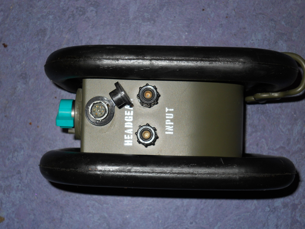
- Connect the radio to an Adapter Telegraph Radio (ATR) by up to 3km of D10 cable and connect a handset or headset to the "HEADGEAR" socket of the ATR and a Teleprinter to the appropriate terminals of the ATR.
In all cases set the UK/VRC-321 to "REMOTE" so it can be keyed from the distant remote station. If frequency changes are required a 2nd operator must be left with the radio, who can be called by the remote station to perform frequency changes as required. To do this:
- Remote sets switch to CALL and then IC
- Radio operator switches from REMOTE to IC and receives frequency change order
- Radio operator changes frequency and tunes in LOCAL mode
- Radio operator sets switch to CALL and then IC to inform remote that set is ready on new frequency
- Radio operator sets switch back to REMOTE
Remote Antenna
It is possible to operate the UK/VRC-321 remote from the antenna. If this is done the TURF should be sited at the antenna base and a long coaxial cable used between the TURF and Radio/SURF. Tuning requires a remote handset and D10 cable so the transmitter can be keyed from the antenna location, or a 2nd operator with VHF talk-back. The limitation is coax loss, but up to 100 metres separation should be possible on the lower HF bands with heavy low-loss coax. The TURF is fairly water resistant if used in this way.
Data Modes
The UK/VRC-321 was designed with RTTY very much in mind and has specific features for data modes
- There is an "RTTY Detector" in the TX path that responds to constant level modulation by reducing output power to a thermally-sustainable 25W
- The UK/VRC-321 supports diversity and duplex operation with a 2nd set acting as receiver
Modern digital modes can be used via the handset sockets. A conventional "ground to transmit" PTT can be used between pins E and F and something like the Tigertronics Signalink USB should be easily connected - spare cables for pressil boxes with a pre wired 7 pin plug are readily available. Unfortunately there is no VOX capability.
Photos
The Author's full collection of UK/VRC-321 photos is at http://moffatig.plus.com/cloudfront/clansman/RT321/
Links
[ Clansman Home ]
[ Radios ]
[ Antennas? ]
[ Audio? ]
[ Batteries? ]
[ Connectors? ]
[ Harness? ]
[ Other? ]
[ Links? ]


