UK/PRC-320
Introduction
The UK/PRC-320 aka RT-320 is the HF manpack of the Clansman family. It is designed as a self contained portable low/medium power HF station that can be carried and used as a single operator either on the march with its own antenna or at the halt with simple wire antennas.
History
The UK/PRC-320 was originally specified as the B20 when the first prototypes were seen around 1970, before the change from Larkspur-era to NATO style model numbers. It was developed and made by Plessey and around 10,000 were made for the UK military. There were also export customers and it was made (in a lower sideband version) under license in the former Yugoslavia as PRC-320/L. Plessey made the 320/1 (with an LSB filter in place of the 100Hz frequency knob, allowing either sideband) and the 320/2 desktop/vehicular radio (a stack of exciter (a repackaged 320/1), 100W PA and automatic ATU) for export.
The UK/PRC-320 was used in the Rhodesia commonwealth monitoring force (Operation Agila, 1978-80) and continued in use until replaced by Bowman in around 2006.
Description
Overview
The radio comprises a single conversion synthesized HF transceiver covering 2 to 30MHz in decade switched 100Hz steps at powers of 3 and 30 watts, an inbuilt manual ATU and a clip-on Ni-Cad battery pack. There is an antenna socket and earth terminal on the top of the set. The set can be mounted on either a standard "rucksack style" carrying frame or the lighter "para" frame with folding stabilising legs. When mounted on the standard frame it can be fitted in a cradle as a "clip in" radio in a vehicle and used with a vehicle mounted whip antenna.
In its basic form CW, AM and SSB (USB only) are supported using local headgear and morse key. The radio can be installed as a "clip in" radio in a vehicle using a 3 or 4 metre whip antenna, and can be operated remotely using a CRL/R box as the interface to telephone cable.
The inbuilt tuner is connected to the transmitter output via a coaxial link and antennas can either be connected to the terminals on the top of the set (if the tuner is to be used) or the coax link can be removed allowing the BNC transmitter output to be connected to a coax-fed antenna (optionally via a non standard tuner - the TURF25W? from the UK/VRC-321 can be used in this way). The inbuilt tuner is intended for electrically short end fed antennas and as well as short whips the tuning table glued to the back of the set has settings for 1/4 and 3/4 wave wire antennas. Dipoles need to be coax fed and cut or unrolled to length.
Summary Data
| Frequency Range | 2.0 to 30MHz by 100Hz steps |
| Frequency Accuracy | +/- 1ppm |
| Power - High | 25 to 30W |
| Power - Low | 3 to 5W |
| Receive Sensitivity | 3.3uV AM 30%mod
0.8uV SSB/CW-W @10dB S/N
0.8uV CW-W @17dB S/N |
| Receive Bandwidth | 6.25KHz AM
3.9KHz SSB/CW
400Hz CW-N |
| DC Input | 24 to 28V (*) |
| Modes | AM, USB, CW |
| TX AF input | 0.4 to 40mV balanced |
| RX AF output | 7mw into 100 ohms |
| Batteries * | 1AH Ni-Cad
4AH Ni-Cad
16AH LiSO2 |
| Battery Life | 12 hours at 1:9 TX:RX ratio with a 3.4aH battery |
| Supply Current | 2 amps mean on high power TX |
| Temperature | -37 to +32 Centigrade (Operating) |
| Weight | 5.1KG without 8.5KG with 4AH Battery |
| Dimensions | 115 x 350 x 250mm without 115 x 475 with 4AH battery |
(from technical Handbook EMER F592)
Note (*):
- A DC power cable with croc clips and reversal protection was available for use with any 24-28V DC source. The 320 has no input protection or filtering and should not be used with vehicle supplies or noisy mains PSUs.
- In vehicles the 320 clip-in was used with a DCCU? to float charge the battery, rather than a direct supply.
The radio has six turret-switched frequency ranges.
The range to be expected according to the EMER F592 was
| High Power Groundwave | 24km / 15 Miles on rolling terrain in W. Europe |
| Low Power Groundwave | 12km / 7.5 miles on rolling terrain in W. Europe |
| High Power Skywave | 500km / 300 miles - (perhaps NVIS or 80m single hop?) |
| Low Power Skywave | 250km / 150 miles - (perhaps NVIS or 80m single hop?) |
No antenna or frequency is mentioned in connection with these range specifications - a reasonable guess would be a dipole for sky wave and the set's own whip for ground wave. The claimed ranges seem appropriate to the lower bands 1 to 2 or maybe 3, whereas I have achieved UK to Sicily on 3W and UK to USA on 30W with a 3/4 wave end fed wire on 14MHz.
Accessories
The following Clansman accessories can be used with the UK/PRC-320
Antennas
The UK/PRC-320 can be used with the following antennas
- Its own 2.8m sectional whip
- 3m or 4m vehicle whip antennas
- 5.5m or 7.9m vertical antennas supported by a fibreglass mast
- 1/4 or 3/4 wave long wires with earth or counterpoise
- Dipoles whether elevated or inverted-V
- Any other 50 ohm fed resonant or broadband antenna
Efficiency and stable tuning of the end fed antennas is greatly improved by use of a counterpoise wire (or ideally several) and these were available in both portable and fixed site versions. A 1/4 wave wire cut to length is an acceptable substitute.
Technical Description
The UK/PRC-320 is a single conversion superheterodyne radio with a fixed single IF of 1.75MHz. Although there is a digital synthesiser the oscillators and front end / PA tuning do not cover the full span in a single range. The radio is therefore band switched in 6 bands using a turret tuner.
| Band 1 | 2 to 3.1MHz |
| Band 2 | 3.1 to 4.9MHz |
| Band 3 | 4.9 to 7.7MHz |
| Band 4 | 7.7 to 12.2MHz |
| Band 5 | 12.2 to 19.1MHz |
| Band 6 | 19.1 to 29.999MHz |
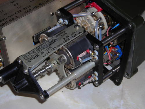
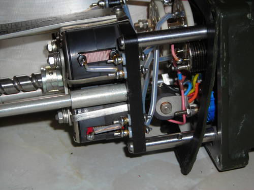
The turret tuner comprises three sets of band-specific circuits
- A VCO for the dial frequency plus 1.75MHz
- A bandpass tuned stage used on TX and RX at the dial frequency
- A transmit harmonic filter
The turret contacts wipe when the switch is turned clockwise - to minimise wear and fatigue of the spring fingers it is best not to turn it anticlockwise.
Construction
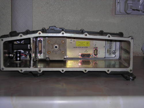
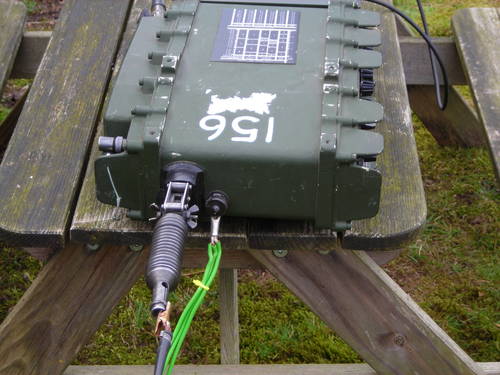
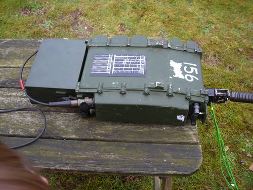
The UK/PRC-320 is built as two chassis attached to the "front" and "back" panels which plug together inside a case which is essentially a flattened tube.
Each panel is sealed to the case with rubber gaskets and secured by an awful lot of socket head bolts. Separation requires removal of all the socket head bolts after which the seals can be broken and the front panel (with the controls) and rear panel (with the PA and audio sockets) can be gently prised out of the case with a blade in the gap between panel and case - they need to be separated about 1/4 inch to come free.
It is very very important to note the position of the band switch before separating as the shaft between the front and rear turrets will only engage if they are in the same position when re-assembled.
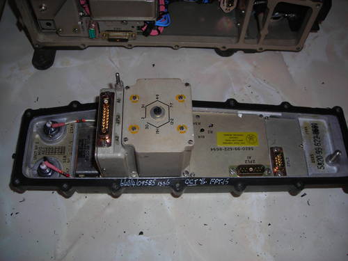
The two panels can be mated outside the set.
(note use of battery extension cable for power supply)
Note that both on the bench and when reassembling it is necessary to be very careful of short circuits as the PSU module is not short circuit protected and there always seem to be loose screws or washers inside, or wires that will be trapped that will be released to do harm after disassembly.
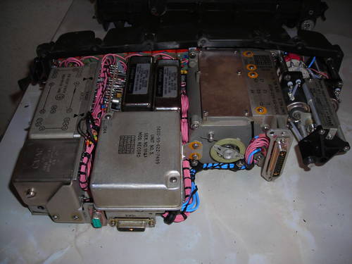
The set has an unshielded motherboard and multiple modules in metal cans which are connected to it. Some modules (like the PSU) are connected via a cable harness or the front/back mating connectors and others are hard wired.
(mating connectors)
(PSU module and wiring harness)
Unfortunately although the connectors are from the Cannon D family they are not readily available sizes and contact combinations.
Synthesizer
The synthesizer is based on medium scale counter integrated circuits and uses an 8MHz temperature compensated reference oscillator. There is a "side step" facility which raises the frequency by 2KHz in SSB transmit mode so that the switch setting represents the centre of the occupied bandwidth (as is the military convention) rather than the carrier frequency which is used in the Amateur service.
The Synthesizer is 1.75MHz (AM) or 1.748MHz (SSB and CW) above the dial frequency. This results in a sideband inversion going from IF to RF stages.
T/R Switching
There is a transmit-receive relay between the reflectometer (SWR Bridge) and the antenna. Further relays are used to transfer the IF Filters between the TX and RX paths. The PTT on AM/SSB and the morse key on CW ground the same pin on the audio socket so the set is inherently capable of break-in operation in CW mode. The synthesizer output does not change between TX and RX mode - the "chirp" reported on some sets going between TX and RX is a PSU regulation problem and may indicate impending failure of the 125V rated tantalum capacitors in the varicap tuning supply.
Transmit
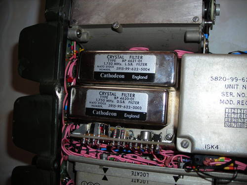
Speech or AFSK data input to either of the audio sockets is amplified to the optimum level by a VOGAD circuit and fed to the IC modulator where they are applied to a carrier derived by digital division from the 1.75MHz synthesizer reference. The PTT and CW key switching is applied in the TX IF stage (called a clipper in the EMERs). Morse keys actually operate the same pin on the audio socket as the PTT so it is possible in emergency to send CW with a microphone PTT. AM is generated as DSB at 1.75MHz (with the carrier re-injected after the balanced modulator), whereas SSB and CW are generated as LSB at 1.748 MHz centre frequency, CW actually being a 2KHz tone input to the modulator. The carrier is 1.7500MHz in each case, since SSB and CW use the lower sideband in the IF stages. There are three separate crystal filters for AM (1.75MHz), USB/CW-W (1.748MHz wide) and CW-N (1.748MHz narrow).
(the third filter is under the chassis)
SSB is produced by filtering a DSB, Suppressed carrier signal. The conversion to final output inverts the sideband so the USB IF filter actually selects the lower sideband at 1.75MHz. The resulting modulated 1.75MHz signal is mixed with the synthesizer output at dial plus 1.75MHz and the difference is filtered to produce the required output frequency and fed to the power amplifier at the back of the set. The rear turret has two sets of filters either side of the PA - the mixer output is cleaned by the same set as the RX input and there is a 2nd harmonic filter after the PA. The power amplifier can produce either 3 or 30 watts depending on the front panel switch setting. The power control circuit and the reverse power protection/SWR meter are part of the same module at the PA output. The ATU, if in circuit, is essentially an L-match with switched capacitors in parallel and a series inductance with switched and (permeability tuned) variable parts. This is specifically intended for end fed electrically short antennas. The reverse power is indicated by the meter in tune mode, which is reverse-reading in the sense that the best match corresponds to the highest reading.
Receive
The antenna signal first passes a diode overload protection circuit and VHF low pass filter and is then amplified by one of a set of bandpass tuned amplifiers (the tuned circuits are in the turret) and mixed with the synthesizer output to produce a 1.75MHz IF which passes through a crystal filter appropriate to the mode in use. At the filter output the IF signal is mixed with the 1.75MHz carrier insertion oscillator to recover CW or SSB. The resulting audio is then amplified and fed to the headphone outputs of the two audio sockets. An audio gate selects a 2KHz tone derived from the synthesizer reference divider chain instead of the receive audio if an error condition (such as decade switch frequency and turret position mismatch).
ATU
The ATU is essentially an L-Circuit with a switched capacitance to ground and a 2-part inductance in series with the end fed antenna - one part switched and one part variable by screwing the core in or out of a fixed coil. This ATU is designed for electrically short end fed antennas and "long" wire antennas should be cut just short of 1/4 wave or 3/4 wave for best results as it cannot match antennas that are longer than resonance.
The ATU works much better if a counterpoise wire is attached to the ground terminal of the set. Tuning as a manpack or on a dry nonconducting surface is difficult and unstable as the headset wire is likely the counterpoise!
The ATU cannot tune dipole antennas very well - the manuals show a V-dipole with one half attached to the antenna socket and one attached to the ground terminal, the radio being on an insulating surface. Amateur operators have found a high voltage capacitor of a few tens or low hundreds of pf between antenna and ground terminals converts the ATU to a "PI" configuration allowing a dipole or doublet with twin feeder to be connected.
PSU
The UK/PRC-320 has an internal switchmode PSU which generates +3V, +6V, +12V and +110V from a 20-28V input. The +3V supply is used by the synthesizer, +6V and +12V by the audio and RF circuits, and +110V by the tuning varicaps for the turret-mounted synthesizer oscillators. Beware that the PSU module has
- No input fuse
- No output protection (so any loose metal inside can short it with expensive consequences - beware loose metal and insulate all mods well)
- 125V tantalum capacitors which do not age well
It is strongly recommended if you have to open the set to replace the tantalum capacitors with modern 150V or higher rated electrolytics - there are two in the VFO assembly in addition to the ones in the PSU.
Block Diagram
LSB Conversion
The PRC-320 is readily converted to LSB operation by replacing the 1.75MHz CIO with one "the other side" of the SSB IF filter. This turns out to be 1.7468MHz. A variety of mods have been published mostly derived from the original G4OEP paper published by VMARS. I have been supplying programmed oscillator chips for this since 2008 and full details are on the LSB page.
There is a ready built module by G3TPJ which is marketed by G4IQE QTHR
This comprises a programmed SG8002 oscillator, a relay and some filtering. It is inserted between the 1.75MHz CIO source and the modulator, being switched into circuit when a 24V supply (usually from the battery check switch) is connected.
Operating
The UK/PRC-320 is a fairly strightforward radio to operate as long as some thought is given to the antenna and ground/counterpoise.
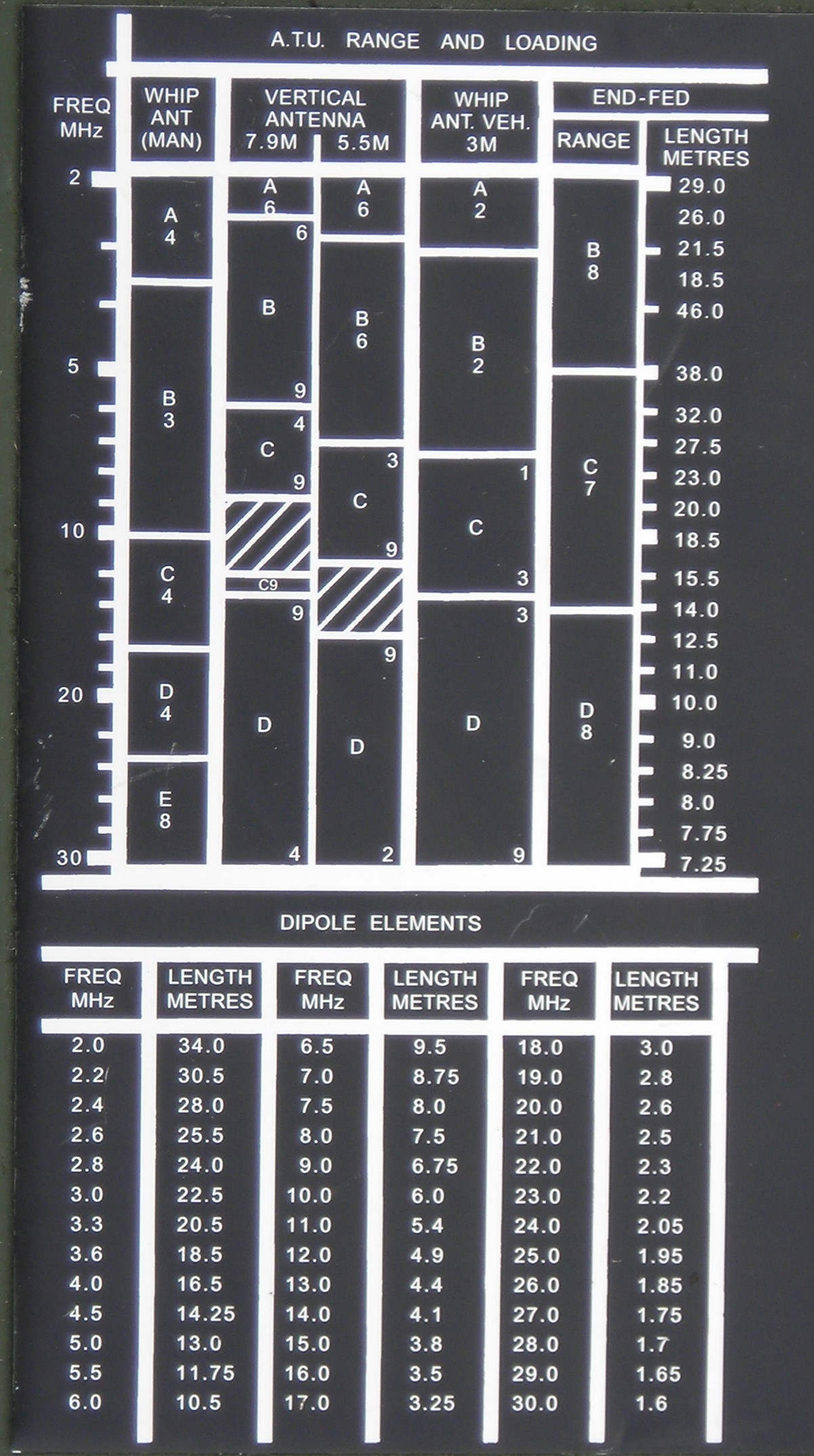
The following diagram may be printed and laminated as a field guide
(click on the diagram to view full size)
Preparation
As a Manpack
Prior to use as a manpack:
- Fit the radio to the carry frame
- Ensure BNC link is connected between TX output and ATU input
- Insert gooseneck adapter at top of set
- Make sure set is switched off
- Attach battery to bottom of set with spring contacts at same end as studs on radio
- Assemble 2.5m whip and insert it into the gooseneck adapter
- Connect headgear and morse key to audio sockets as required
As a fixed station with a dipole
Prior to use as a fixed station
- Remove BNC link - it is attached to the radio by a cord so cannot be lost
- Connect coax from dipole centre to TX output BNC
- Make sure set is switched off
- Connect battery to bottom of radio directly or using a battery extension cable
- Connect headgear and morse key or data terminal
If using an external ATU then this should be connected between the TX output and the antenna coax using a BNC patch lead.
Prior to use in a GS Landrover
If using the 320 in a GS landrover (or an FFR with a clip-in frame for manpack radios):
- Fit a 3m or 4m whip antenna to a side stalk on the same side as the cradle
- Place the manpack in the cradle and secure the clamps
- connect the antenna to the terminal beside the gooseneck with a single wire, which must be routed clear of all metalwork
- make as short and thick a connection as possible from the earth terminal on the radio to vehicle metalwork
- Make sure the radio is switched off
- Fit a 1AH or 4AH rechargeable battery to the bottom of the radio
- If the vehicle has a DCCU connect the battery to the DCCU using the special 4-conductor charge cable
- Connect headgear and morse key (or data terminal) to the audio sockets
Pre-use checks
These checks should be done at the start of the day or to test a new (to you) RT-320
- Main switch should be at OFF (get fresh battery if not!)
- Rotate band switch clockwise to range containing desired frequency
- Set desired frequency on decade switches
- Set desired mode on mode switch
- Set ATU range and load switches according to table on top/back of set
- Move main switch to BATT CHK and verify meter reading is 4 to 5
- Move main switch to LP and check that
(a) Tone stops within a few seconds and
(b) Signals are heard (assuming the band is open and the antenna connected)
NOTE: If the band switch and frequency set on decade switches are not matched, then a permanent tone will be heard. This is a user warning and not a fault.
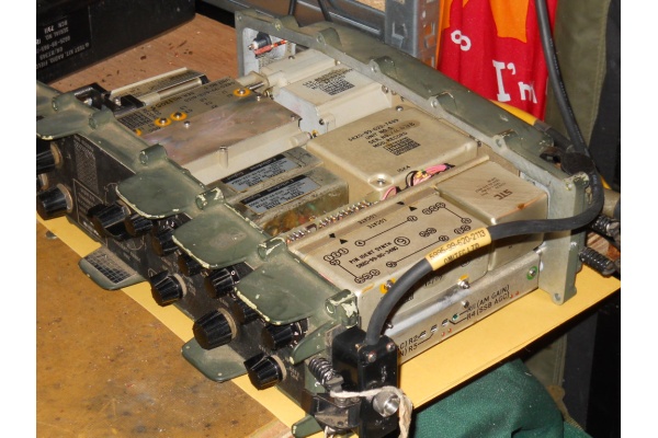
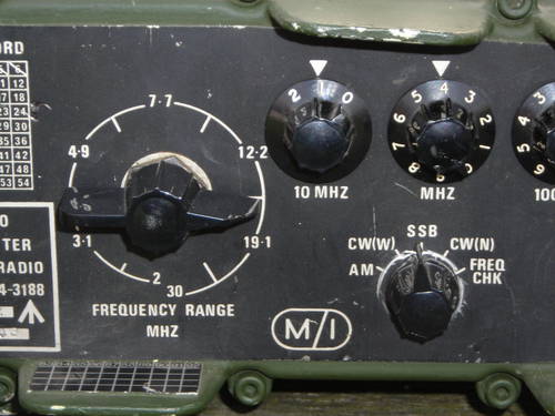
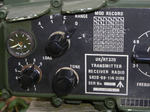
Controls
The UK/PRC-320 has the following controls
- Frequency Range Switch
- Frequency setting decade switches
- Mode switch
- Gain (volume) control
- Main Switch
The Mode switch
has the following settings (in order clockwise):
- AM - Full AM with carrier
- CW(W) - Morse code with SSB-equivalent IF bandwidth and 800Hz BFO
- SSB - Upper sideband with 3KHz bandwidth, dial 2KHz above carrier
- CW(N) - Morse code with a narrow filter centred on the dial frequency
- Freq Chk - used for zero beating a known standard frequency like WWV
The main / power switch
has the following settings (in order clockwise):
- OFF - power is completely off
- ANT - Antenna tuning - low power mode with SWR protection disabled and meter reads max for lowest SWR
- LP - Low power - 3 to 5 watts out and meter reads power
- HP - High Power - 25 to 30 watts out, meter reads power
- BATT CHK - Meter reads battery state - 5 is at least 28V so around 4.5 volts per division. Radio is in HP mode
Note that many LSB conversions are switched to LSB by using Batt Chk mode so power measurement is not available when using LSB.
The ATU has three controls
- Range - sets shunt capacitance
- Load - sets switched part of series inductance
- Tune - sets variable part of series inductance
Using the UK/PRC-320
Using a whip or wire antenna
When using end fed antennas refer to the top half of the tuning chart
(Click on the image to see full size)
Connect the antenna and ground to the socket and screw terminal at the top of the set
Connect the battery to the bottom of the set
and the handset(s) or headset(s) or morse key to the connectors at the battery end of the rear panel. Note that these are keyed and the collar will only slide forward and turn when they are in the right position.
- After pre-use checks set main switch to ANT
- If not already done set ATU controls to correct positions for operating band based on the chart
- Move mode switch to CW-W
- Press morse key or headset PTT and adjust TUNE for maximum meter reading.
- Move Mode and Power switches to desired mode and power level
- Operate the radio - small frequency changes can be made without retuning
Note that the whip antenna tuning seems to need a very good ground (like resting on a metal vehicle) and it is much more stable and reliable with a counterpoise wire / drag wire although you may have to adjust the load and range switches for best match regardless of what the chart says !
Using a dipole or other coax fed antenna
- After pre-use checks set main switch to ANT
- Move mode switch to CW-W
- Press morse key or headset PTT and adjust antenna length or external ATU for best match. An external Power/SWR meter is recommended although it is possible without.
- Move Mode and Power switches to desired mode and power level
- Operate the radio - small frequency changes can be made without retuning
Hints
Opening the 320
When opening the 320 be sure to record the position of the frequency range switch - if it is turned while the front and back halves of the turret are separated the radio can be reassembled but the "screwdriver" shaft will not engage the back half and the radio will only tune on one band where the front half and back half are aligned.
Extending the life of the band switch
It is claimed that there is less stress on the brass fingers which connect between the fixed and rotating halves of the turret tuner if it is always rotated clockwise.
Signs of impending failure
If you hear stations "coming into tune" after an over or other stations report chirp on CW, then the 320 is losing regulation on the 110V varicap tuning supply and the tantalum capacitors should be replaced without delay.
Land Rover Installation
Although the 320 is a manpack set, a cradle that held the old-style tubular carry frame could be fitted to the dexion in a landrover. The requirements for a landrover mounted 320 station are
- Fit dexion above the rear bulkhead
- Optionally, fit a 14 or 24V DCCU in the middle of the dexion. If the vehicle is not FFR connect a Clansman LT box to the 12v battery with an inline fuse - 10 amp is big enough. If it is FFR there should already be a 24V DC supply.
- Fit a clip-in cradle to the right of the DCCU (so the RT320 controls face into the landrover rather than towards the wall or canvas). M8 bolts with nylock nuts work well.
- Attach the 320 to a tubular carry frame (see below)
- Clamp the carry frame into the cradle
- Fit a right hand antenna stalk to the side of the vehicle
- Fit a No.31 antenna base to the top of the stalk. DO NOT use one with the cylindrical VHF adapter and BNC socket
- Insulate the wire coming out of the base with Clansman plastic bowl insulators and feed it inside the landrover canvas (use a plastic grommet if no suitable flap exists) - I had a hard top landrover and used a SO239 barrel connector with 4mm plugs each side as a feedthrough. Connect the wire to the antenna terminal of the 320.
- Fit an earth strap between the earth stud on the 320 and the dexion.
- Connect the DCCU to the charge socket of the RT320 battery
- When parked and ready to operate fit a 3m or 4m whip to the No.31 socket
Fitting the 320 to a carry frame
Unlike the UK/PRC-351 the RT320 does not directly fit the tubular and para-style frames. Two metal bars have to
be screwed to the back of the 320 and the captive screws on the frame mounting plate then screw into these bars.
Use of external amplifiers and tuners
The RT320 will work well with external amplifiers that require 3 to 5 watts of drive to reach full output. The 320 should be set to LP mode as there is no ALC. An amplifier input can be connected directly to the TR BNC connector.
The TURF-25W? ATU from the UK/VRC-321 is an ideal ATU for use with the 320, although the ATU meter, being powered by the 321 over the coax inner, is not operational and a civilian SWR/Power meter should be used between the ATU and the radio TR socket.
The LDG 100 or 125 watt automatic ATUs work well with the 320, even at low power output in ANT mode. Just connect the ATU between the TR socket and antenna and hold the key or PTT down in ANT mode until the 320's meter shows maximum. I use an LDG Z100 Pro II in an ammo box with a Yuasa sealed lead acid battery which gets good results with a near 1/4 wave vertical and 1/4 wave counterpoise wires on 40m.
Photos
The photo gallery linked to this article is at:
And some newer photos are at
Links
[ Clansman Home ]
[ Radios ]
[ Antennas ]
[ Audio ]
[ Batteries ]
[ Connectors ]
[ Harness ]
[ Other ]
[ Links ]