UK/PRC-319 aka RT319 or BA1302

(Click on image for picture library)
Introduction
The UK/PRC-319 is an HF and low VHF manpack transceiver covering 1.5 to 40MHz CW, USB and data modes at 5 or 50 watts. It was intended for use by special forces on long patrols and was optimised for low probability of intercept and flexbility - to some extent at the expense of convenience of the amateur operator. Although some web sites describe it as such, the 319 is not a true spy set as built to military standards of toughness with no attempt to hide its origin. It is best regarded as the end of a line of sets used by paratroops and forward patrols for calling home starting with WS76/R109 at Arnhem through the Station Radio 128 and UK/A16 aka UK/PRC-316 in the 1950s, 1960s and 1970s.
The radio has no continuous tuning capability - it has 10 independent pairs of RX and RX frequencies which are pre-loaded in memories and then recalled for use. In amateur terms it is only easy to use for nets or skeds, and a separate receiver is needed to "find" stations before tuning to them (a process that requires some 28 key presses!).
It is believed to have been used by the UK, Australia, New Zealand, the Netherlands and possibly the USA. The 319 is somewhat later in design than the true Clansman radios and is microprocessor controlled with an embedded Intel 8085 CPU in the main set and a separate processor in each of the automatic ATU and the optional electronic message unit. The user interface comprises a 2 line 7 segment LCD and a 20-key keypad on each of the main set and the EMU plus some traditional rotary controls.

Display

Keypad

Controls
HISTORY
The RT319 or UK/PRC-319 was designed by MEL (Mullard Equipment Ltd, a Phillips subsidiary then and now absorbed in Thales) in the UK and marketed in the USA by TRW.
In British service it appears to have replaced the combination of UK/PRC-316 HF radio and AN/GRA-71? burst sender from about 1988 - (Author's note: I have never seen any description of an equivalent configuration based on a UK/PRC-320 and burst sender to cover the gap between my 1979 dated AN/GRA-71 and the 319, but would be happy to be corrected). At the expense of considerably greater weight than the UK/PRC-316 it allowed coverage of the upper HF and lower VHF bands, and the digital EMU allowed message reception as well as burst transmission. The primary end users seem to have been the SAS, SBS, SRR and related units who required long range communications with a low probability of discovery. Whether through cost or the greater weight and complexity it never supplanted the UK/PRC-320 as the general issue HF manpack of the Clansman era.
The UK/PRC-319 was used in British special operations from the 1st Gulf war through at least to Kosovo (KFOR) and presumably most conflicts between those dates.
They appear to have been withdrawn from service sometime around 2006/7 - they appeared on the surplus market before 2010 at the same time as the mainstream Clansman sets, but even a 300-Baud message of 2 groups lasts several seconds and they must have been at severe and growing risk of detection by technically sophisticated adversaries well before the turn of the century based on the capabilities of digital sampling test gear at that time. Probably by 2000 the operators only remained safe from discovery against non-state adversaries with limited DF and EW capabilities and then as much because of the extended frequency coverage above 30MHz as burst transmission. Interestingly some pre-Bowman HF fequency hoppers (Racal Panther H and Harris Falcon) appeared as surplus by the same route at around the same time so probably the 319 represents the end of line for HF patrol sets with burst transmission as a "low probability of detection" communications solution.
Several websites quote a total build of 350 radios - having said that the author has radio no. 1762 and TURF no. 1761 so the 350 may not be the whole story.
Description
Physically it consists of four units with MEL part numbers in the BA1300 series (three of which are optional) and a battery
- BA1302: The base radio - can be used on its own with matched antennas such as pre-cut dipoles
- BA1303: The Tuner Unit Radio Frequency (aka TURF) - is an automatic ATU end fed antennas between 3.5 and 40MHz, can also match coax fed antennas
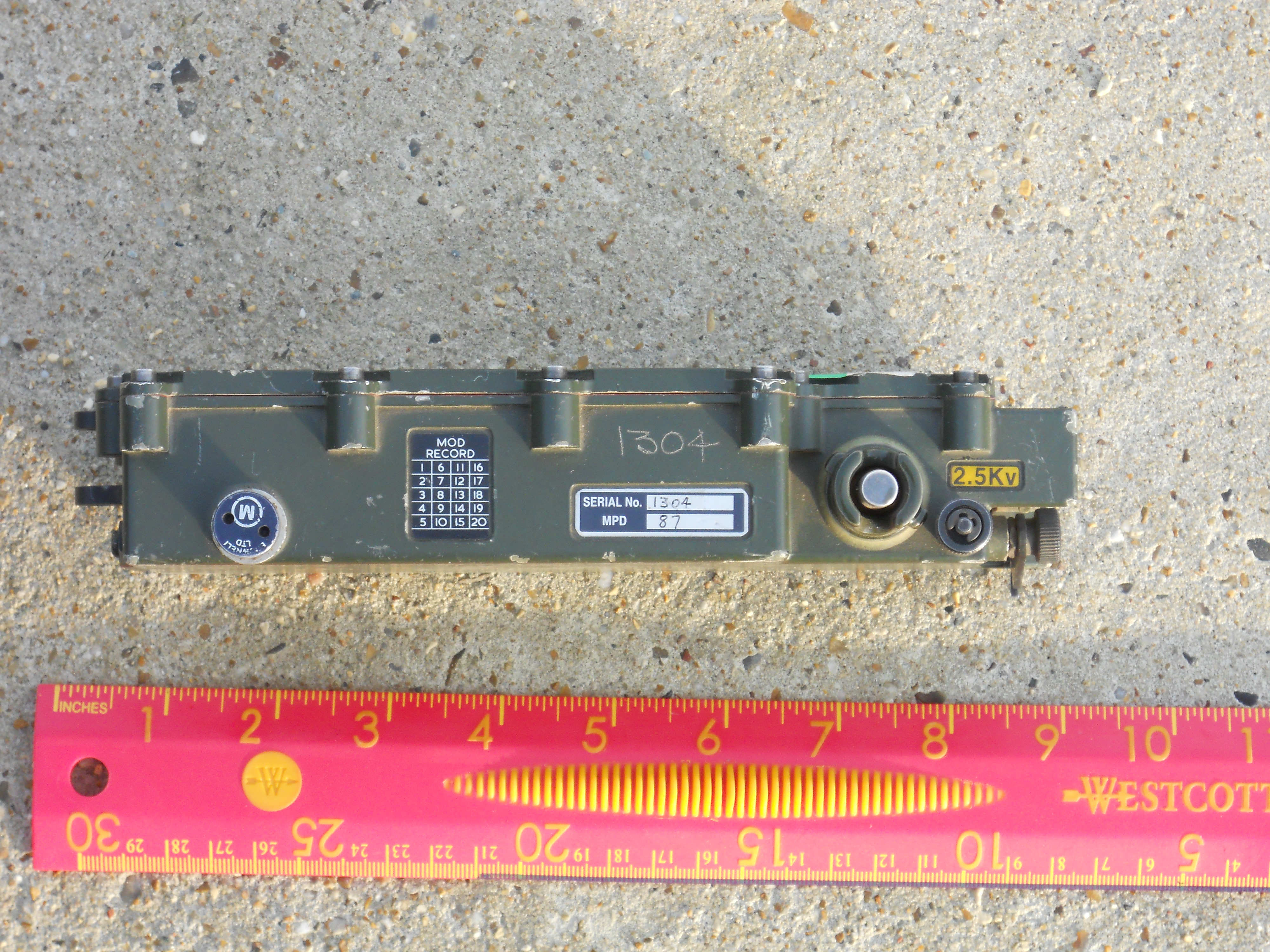
- BA1304: The basic Electronic Message Unit - can send and receive decimal numeric burst messages using the STANAG 4202 air interface at 75, 150 or 300 baud with basic selective calling features
- BA1305: The TURF extender - provides additional switched inductors for with the TURF below 3.5MHz
All components, if unopened and unmolested, are waterproof.
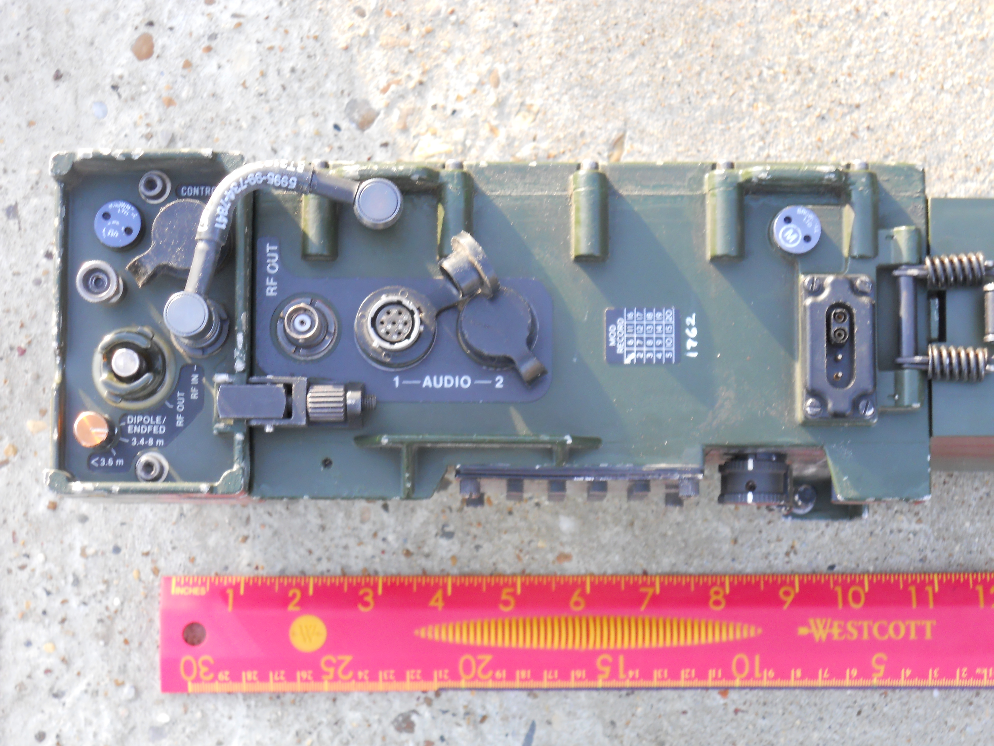
The core of the set is the BA1302 radio which has the keypad, controls, RF audio connectors and an empty cavity for the EMU.
The user interface comprises a rotary gain control, power and mode switches, a 20 key keypad and a 2 line LCD display. Normal Clansman "24V" batteries can be used (clamped to the bottom of the BA1302 body) as can Clansman headgear and morse keys (connected to the two 7 pin sockets on the right hand side).
Audio socket 2 supports a data terminal instead of headgear and a Clansman battery-like connector is provided on the side of the set to power the DMHD data terminal. The RF connector is a BNC mounted on the right hand side above the audio connectors. The BA1302 has an internal STANAG 4202 modem and provides a clock for the EMU or other compatible data terminals. Other data terminals can be connected via audio socket 2 in X mode. The internal modem is connected to a socket on the side of the EMU bay and operates at 75, 150 and 300 Baud as selected by front panel mode switch.
The BA1303 TURF clamps onto the top of the basic BA1302 radio, and the BA1305 TURF extender clamps on top of the TURF - so depending on operatirg fequencies and antennas to be used one or both can be removed to save weight
The TURF is powered via the coax from the radio and can be separated from the radio to be located at the antenna feed point. A short 7 pin link cable plus ground and RF wire links connect the TURF to the TURF extender when in use. The antenna is connected to the TURF extender when it is in use. There is no provision for mechanical attachment of a whip antenna to the set - the provided whip is intended to be used at a halt as a ground spike antenna connected to the TURF and used with a counterpoise wire laid on the ground. The purpose-made backpack is reported by W0RW to have had a pocket for the antenna base so it could be operated pedestrian portable, with a drag-wire counterpoise. My radio rucksack isn't the UK/PRC319 version alas :(
The BA1304 EMU fits a cutout in the front panel, being inserted from the side and locked in place.
The EMU has an internal battery (a 9v alkaline PP3 can be used) so it can be removed from the set for convenience in message entry. The EMU has its own 20-keypad and 2 line LCD. Both the EMU and the main radio LCDs have hinged protective covers.
Summary Data
| Module | Description | Weight (KG) | Dimensions HxWxD mm |
|---|
| BA1202 | Transceiver | 3.4 | 200x210x103 |
| BA1203 | TURF | 1.3 | 64x205x105 |
| BA1204 | EMU | 0.7 | 165x95x48 |
| BA1205 | TURF Extender | 0.5 | 49x212x90 |
| Battery | (16/5/4AH) | varies | 130x180x80 approx |
| TOTAL | excl battery | 5.9KG + Battery | 450x210x105 |
Accessories
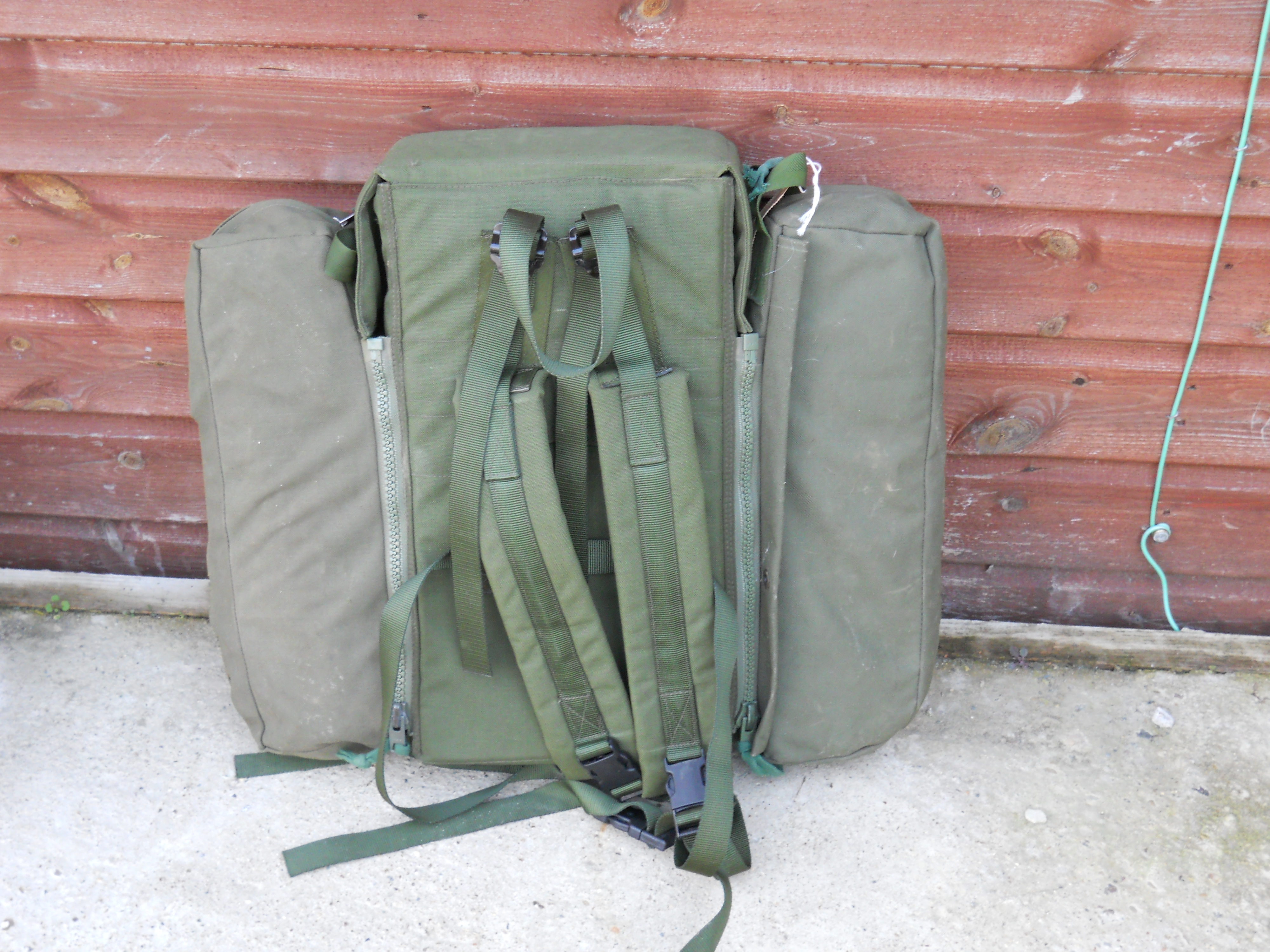
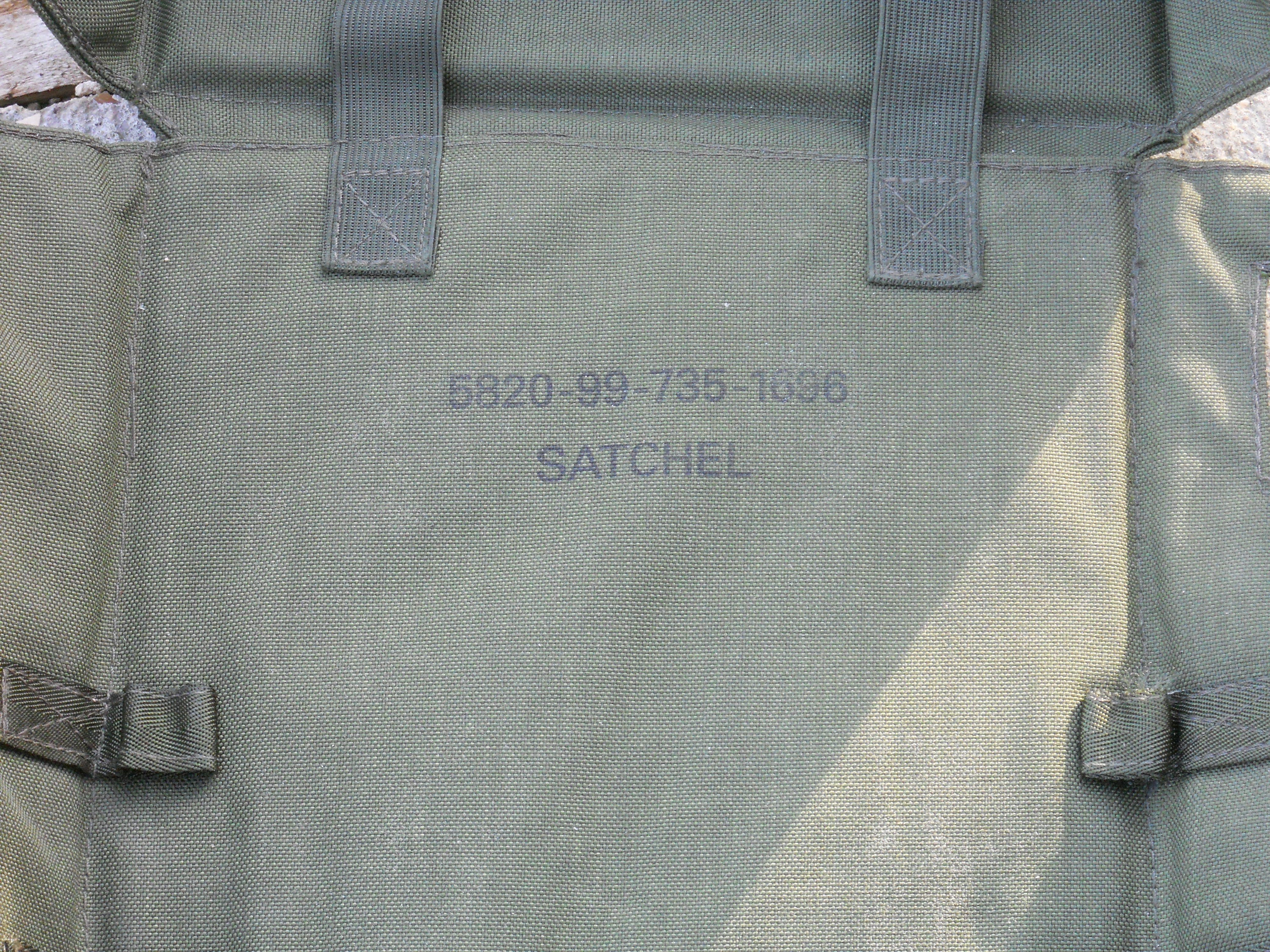
The UK/PRC-319 had a custom radio rucksack NSN 5820-99-735-1696 with two side pockets and a canvas "tidy" for the various accessories specific to the set:
The accessories comprised
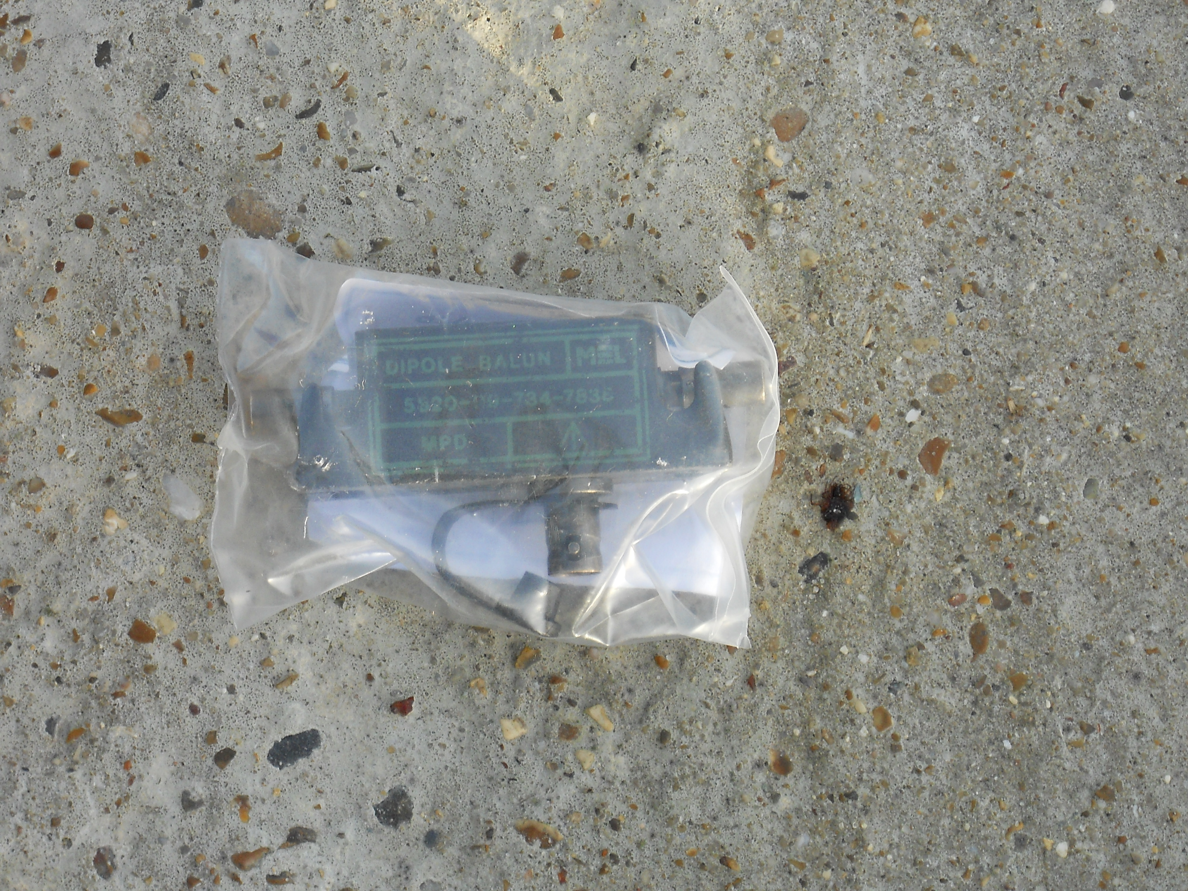
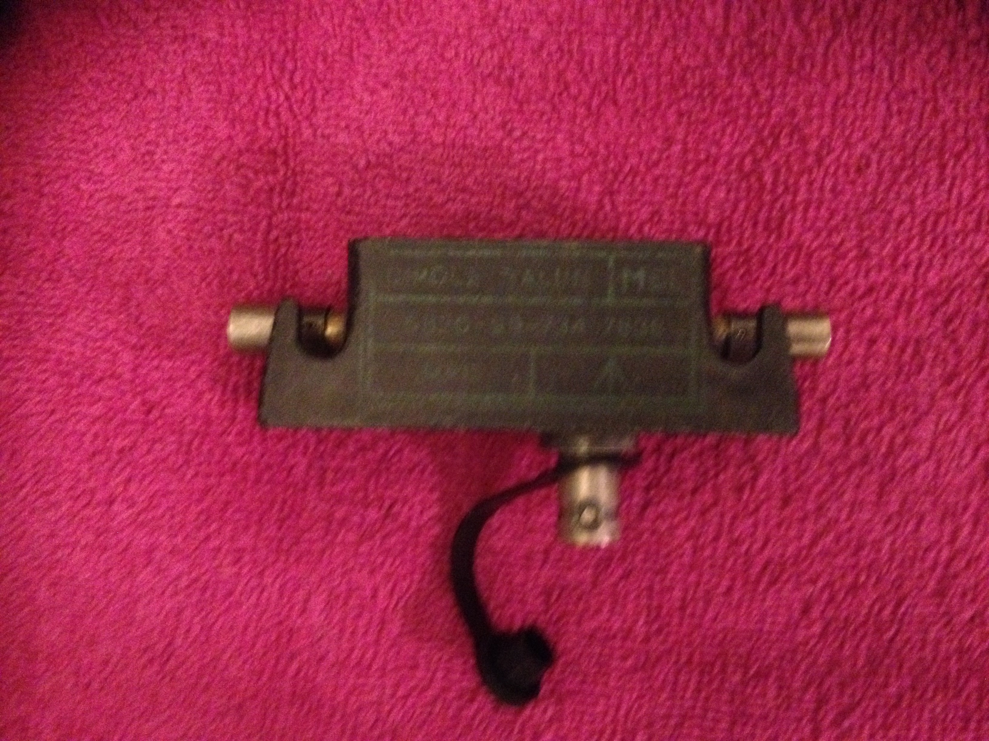
- A Dipole Centre BALUN
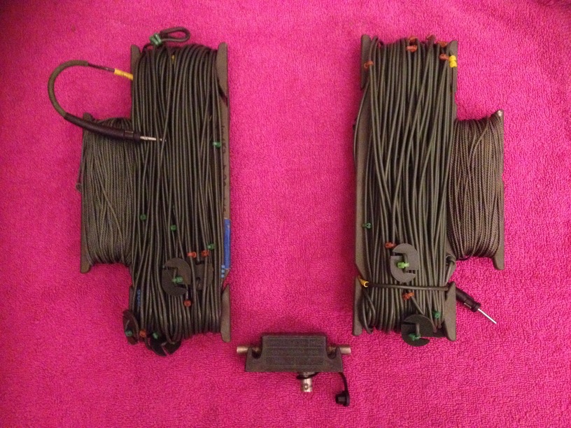
- A pair of dipole wires that can be unrolled to length for the frequency in use
- A counterpoise
- 5 and 7 metre end fed wire antennas
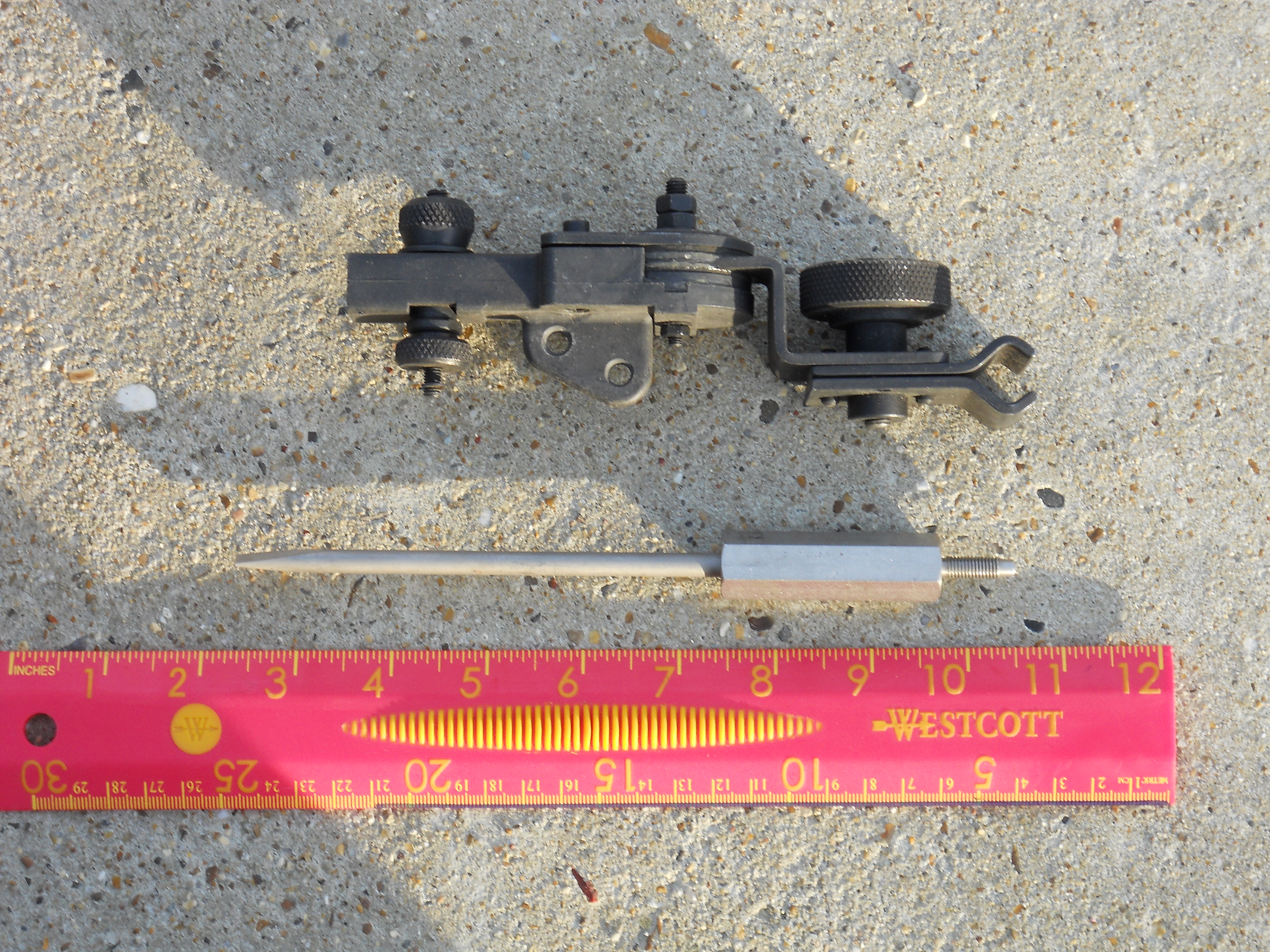
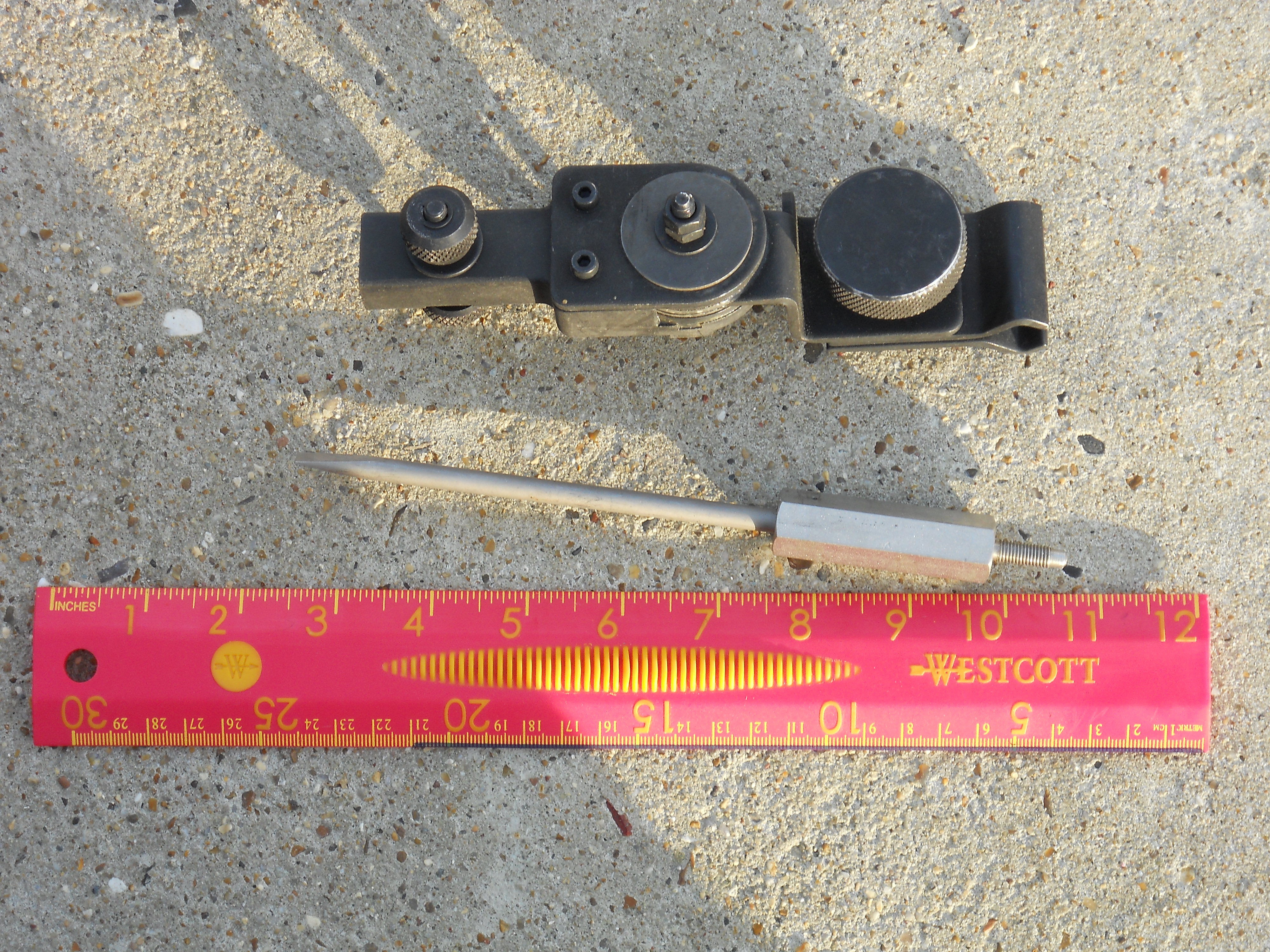
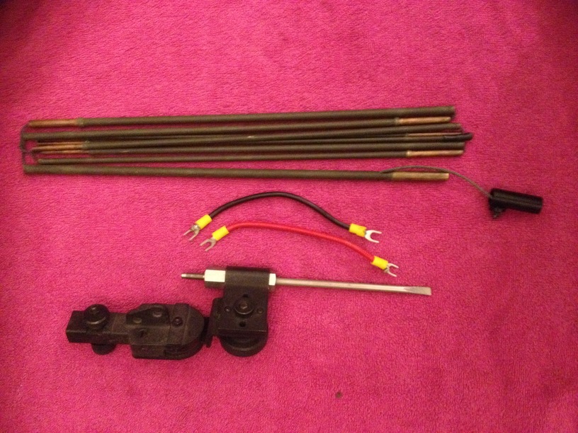
- A ground spike which doubled as a screwdriver
- A 2.8m sectional whip antenna
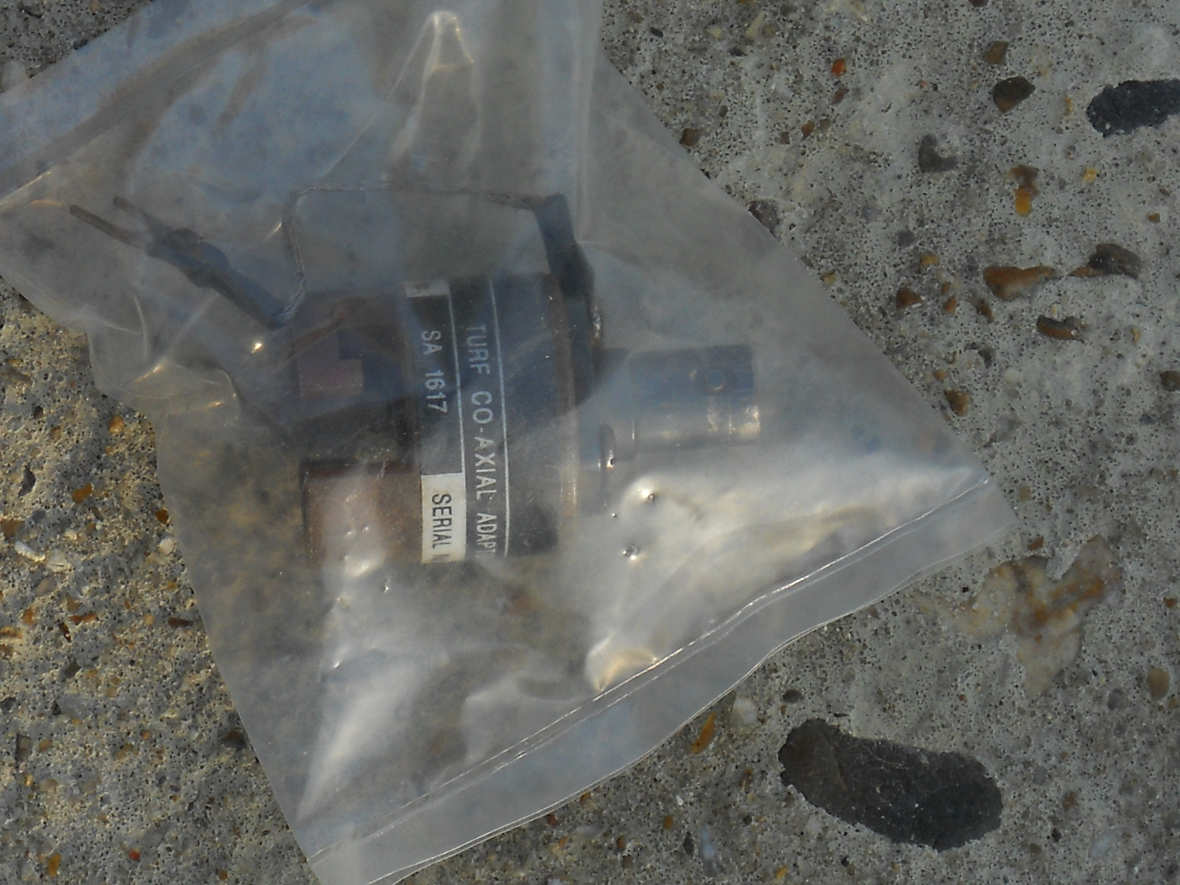
- An antenna clamp which allows the whip to be mounted on the ground spike
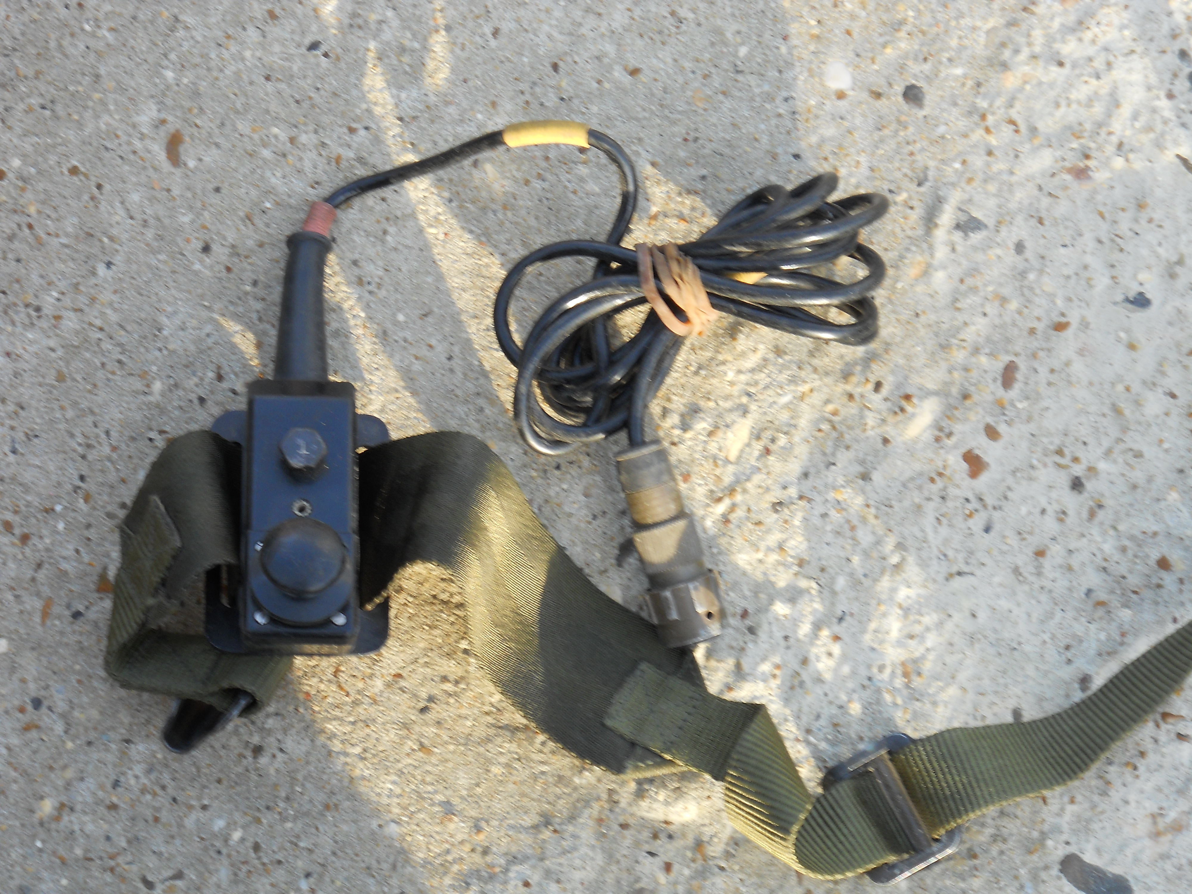
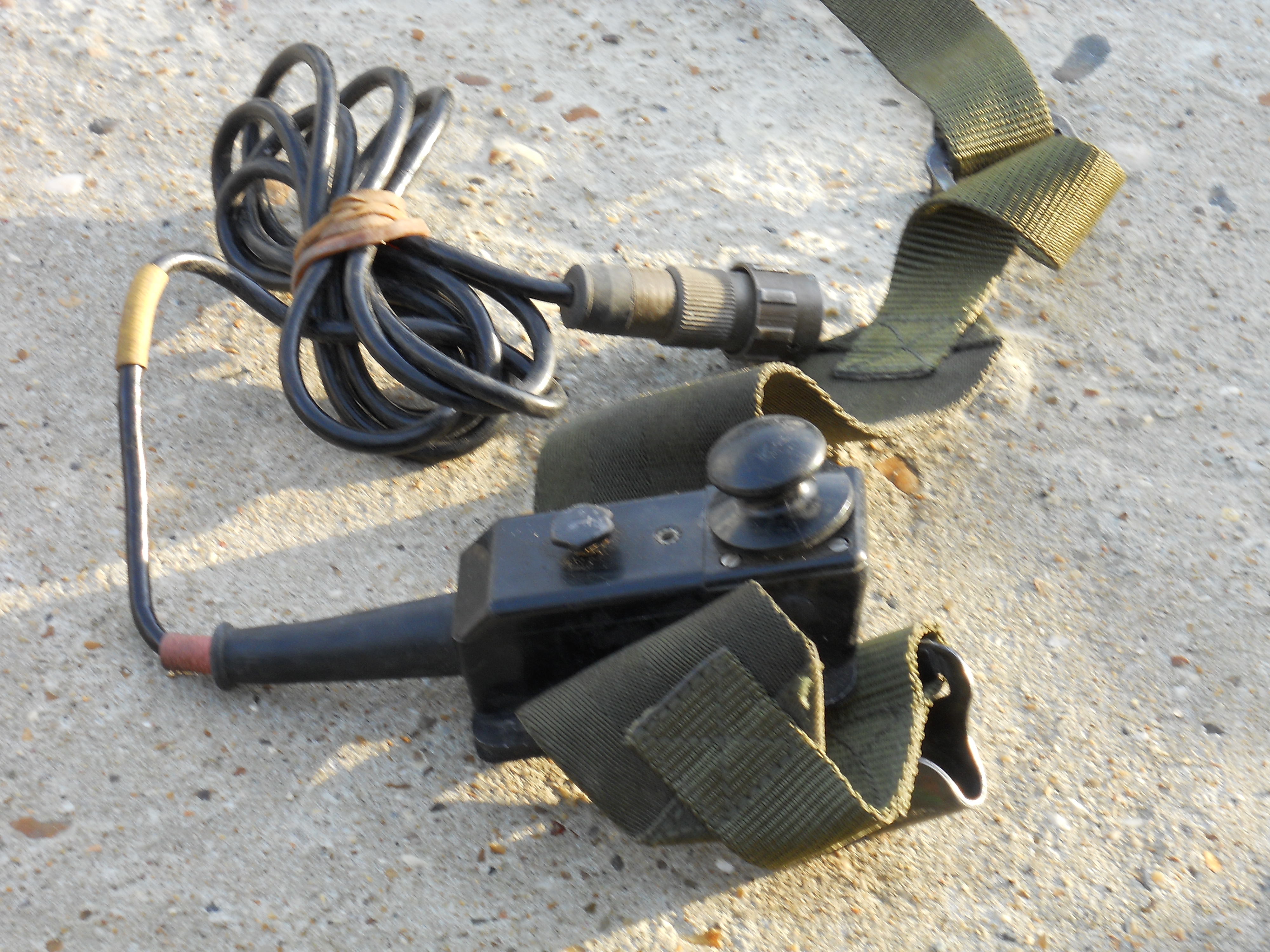
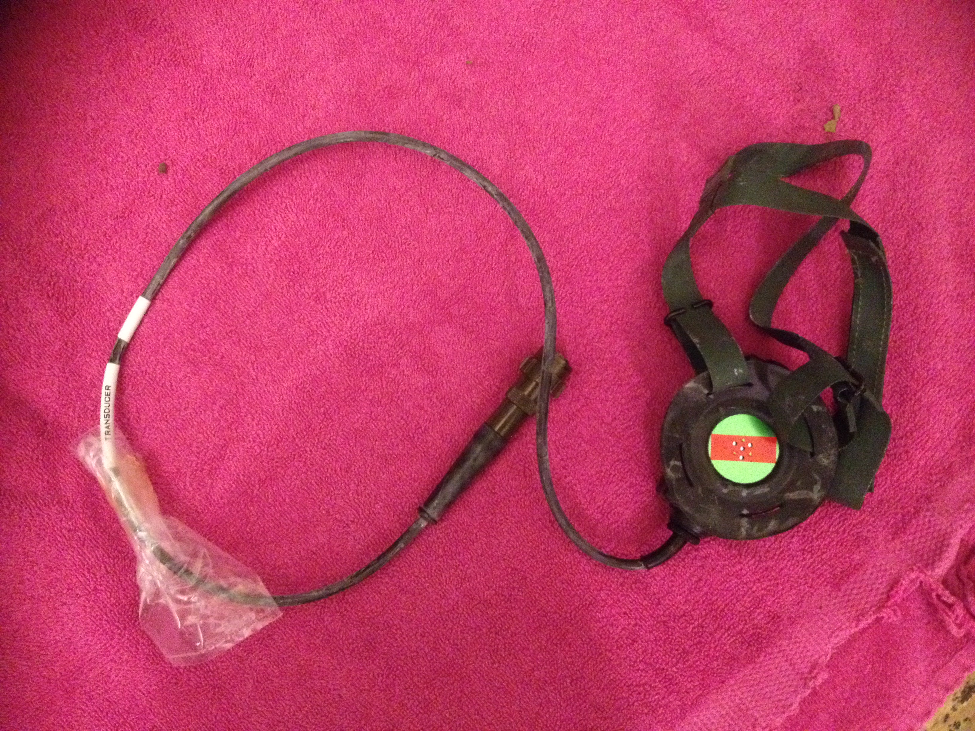
- A single earphone transducer which also can be used as a microphone (the PTT is on top)
- A short extension lead which allows the EMU to be separated from the set
- Connecting leads for radio to TURF and TURF to extender
Please click on the following images for larger views of those that I have been able to photograph
Operating
This section is a precis of the UK/PRC-319 user manual at www.pa3ect.eu and the BA1304 EMU manual at www.cryptomuseum.com.
Controls
The controls are
- Analogue volume control marked "GAIN" - this behaves differently in CW, SSB and data modes. In CW it is both an AF and RF gain control. In SSB it is AF only. In DATA and X modes the AF levels to the EMU or AF socket 2 respectively are preset.
- Power switch with positions "OFF", "TEST", "LP" (5W), "HP" (50W), "BAT CHK" (battery check) and "S/BY" (standby)
- Mode switch with positions "CW", "VOICE" (SSB USB), DATA 75/150/300, and X (for an external data terminal in audio socket 2)
- 20-key keypad with keys "0" through "9", "STORE", "R" (Receive), "T" (Transmit), "TEST", "TUNE TURF", "CHANGE", "R/T IN USE", "ILLUM" and up/down arrows. "ILLUM" operates LED lamps at either side of the display. The arrow keys set the light level when "ILLUM" is pressed. If only they were incremental tuning ;)
Preparation
Prior to operating the set
- Make sure the power switch is off - note that it needs to be pulled out to turn to or from the off position
- Connect the battery, headset and a dummy load or an antenna
- Pull out and turn the power switch to "BATT CHK" - voltage should be 28-30V on receive
- Press PTT - the on load voltage will be shown after about 10s but unlike the UK/PRC-320 equivalent no RF is transmitted
- Move the power switch to "TEST" and the mode switch to "CW" - the display should become visible
- Press "R" then "TEST" on the keyboard and wait for "BITE PASS"
- Press "T" then "TEST" on the keyboard and wait for "BITE PASS"
- Move the mode switch to "DATA 75" and press test. Tones will be heard and the display will show alternating "1" and "0"
Using the RT319
To operate the radio:
- Set the mode to CW or Voice as required
- Move the power switch to LP (Low Power)
- Program Receive Memory 0
- Press "R" then "0"
- Enter the frequency e.g. 071870 for 7.1870 MHz or 142200 for 14.220 MHz
- Press "STORE"
- Press "R" then "0"
- Press "Change" to make R0 the active receive channel
- Program transmit memory 0
- Press "T" then "0"
- Enter the frequency e.g. 071870 for 7.1870 MHz or 142200 for 14.220 MHz
- Press "STORE"
- Press "T" then "0"
- Press "Change" to make T0 the active transmit channel
- If you have a TURF connected then tune it
- Connect the antenna (and counterpoise if using an end fed antenna) to the TURF
- Make sure the TURF antenna switch is set for the correct length range
- Press "R" then "TUNE TURF" to tune on the RX frequency
- Press "T" then "TUNE TURF" to tune on the TX frequency
- The LCD should no longer show the "TUNE" message
- Press "T/R IN USE" to confirm frequencies in use
- Repeat for R1 through R9 and T1 through T9 if required
It is now possible to operate the radio normally using the handset or a headset and morse key. Any frequency pair can be selected using the sequence
- Press "T" then the channel number
- Press "Change"
- Press "R" then the channel number
- Press "Change"
- Press "T" then "Tune TURF" and wait for the TUNE message to go away
- Press "R" then "Tune TURF" and wait for the TUNE message to go away
- Press "T/R in Use"
Note that
- There is no clarifier or fine tuning (the keypad arrows are an LCD illumination brightness control).
- The radio memory is lost if it is turned "OFF" - use the "STANDBY" power setting to retain the memory.
- The forward and reverse power are displayed as horizontal bars in the lower display row when transmitting - forward power is the upper row.
Antennas
The UK/PRC-319 supports four antenna configurations by design (and no doubt others are possible):
- Supplied 2.4m whip mounted on ground spike and connected to TURF, used with counterpoise
- Supplied 5 or 7m end fed wires for middle or lower HF bands (used with counterpoise)
- End fed long wire, optimally just short of 1/4 wave or just short of 3/4 wave connected to TURF (used with counterpoise)
- Dipole fed with coaxial cable - connected to TURF or direct to set using a supplied BALUN
Battery Change
To preserve the memory contents always change battery using the following method
- Move the Power switch to "STANDBY"
- Disconnect the battery
- Connect the new battery
- Move the Power switch back to one of the operating positions
The manual does not specify how long the battery can be disconnected in standby mode so no avoidable delay should be allowed between steps 2 and 3.
EMU Operation
It is clear from the TRW promotional video and other sources that the 319 was intended for use with two EMUs - one disconnected for message preparation and one connected to receive messages - if necessary unattended. The EMU functions approximate GSM phone text messaging but limited to numeric messages and 6-digit numbers.
The EMU can be tested and programmed on or off the radio. When powered up it should display something like
F 0001
P 0001
The actual numbers are dependent on the memory contents when powered on - both numbers will be zero after clearing it. First save the callsigns:
- Switch EMU on
- Press "SEL RX" button
- Press "SP" button
- A C will appear in the top row of the display. The 2nd row will show "1 001". Enter the 6 digit callsign which will be displayed in the bottom row.
- Press "NEXT GRP" to store the callsign and prepare to input the next one - the previously entered one will move up to the top row.
- Press "SEL RX" again to close the callsign store and save changes
- Press "SEL RX" then "SP" then "CLEAR" twice followed by "SEL RX" to clear the store
Note that some documents suggest a limit of 3 receiver callsigns. The EMU only supports numeric messages which are not well suited to amateur traffic. The original owners would have used agreed short codes, one time pads or external devices to encode their messages. In Amateur service it is not permitted to use secret codes. At least in the USA the problem is solved by using a public code table - one such was developed by Paul Signorelli W0RW and is called RWOP. In simple terms letters A to Z are encoded as 00 to 26, numbers 0 through 9 as 80 to 89 and space as 00. To prepare a message
- Switch EMU on
- Press "SEL TX"
- Press "1" or "2" to choose which store to save the message in. The display will show "t" on the top row and "1 001" when ready to enter block 001 in store 1
- Enter a callsign as the first group or 000000 for broadcast and press "NEXT GRP"
- Enter 6 digit data groups pressing "NEXT GRP" after each one
- After completing the final group press "NEXT GRP" then "EOM" then "SEL TX"
Some documents suggest a limit of 9 groups per message. If the store is full the EOM mark (three horizontal lines) will be shown and cannot be overtyped. To erase a message either overtype it by repeating the above process or
- Press "SEL TX" then the store number
- Press "CLEAR" twice within 2 seconds
- Press "SEL TX"
To send a stored message
- Connect EMU to UK/PRC-319 if not already connected and switch EMU on
- In amateur service transmit callsigns in CW or voice before sending data
- Select data speed from 75, 150 or 110 on UK/PRC-319 mode switch
- Press "SEL TX" then "1" or "2" to choose the store
- Check that the expected message is displayed
- Press "TX" after which a "^" mark appears beside the printed "S" at the top of the display. The TURF is tuned automatically before the burst is transmitted.
Contrary to the manual it does not always say "FAIL" if it fails - I have had bad connections between the EMU and 319 that failed silently. A successful transmission is also confirmed by data tones in the headset during the transmission.
Received messages are automatically saved if the 319 and EMU are on and the correct data speed has been selected on the mode switch. There will be a "^" indicator beside the printed "R" or "B" at the top of the display, if a regular or broadcast message has been received. To read the message(s)
- Press "SEL RX" after which the display will show broadcast and regular message counts on the top and bottom rows
- Press number of store (1 to 9) to read regular addressed messages or "0" to read the one broadcast message the set can store
- Press "NEXT GRP" to advance to the next group until the 3-bar EOM mark is seen
Note that more than 9 regular messages can be stored but only 9 can be accessed. You must delete some visible messages to get to the rest. If the "^" indicator next to the printed ">" at the top of the display is lit, the store is full and received messages will be lost unless something is deleted. Press "CLEAR" twice within two seconds, while reading a message, to delete it.
If a message is incompletely received, then there will be a "^" segment lit beside the printed "E" at the top of the display and the garbled digits will be replaced by "-" if some parts of the message can be decoded.
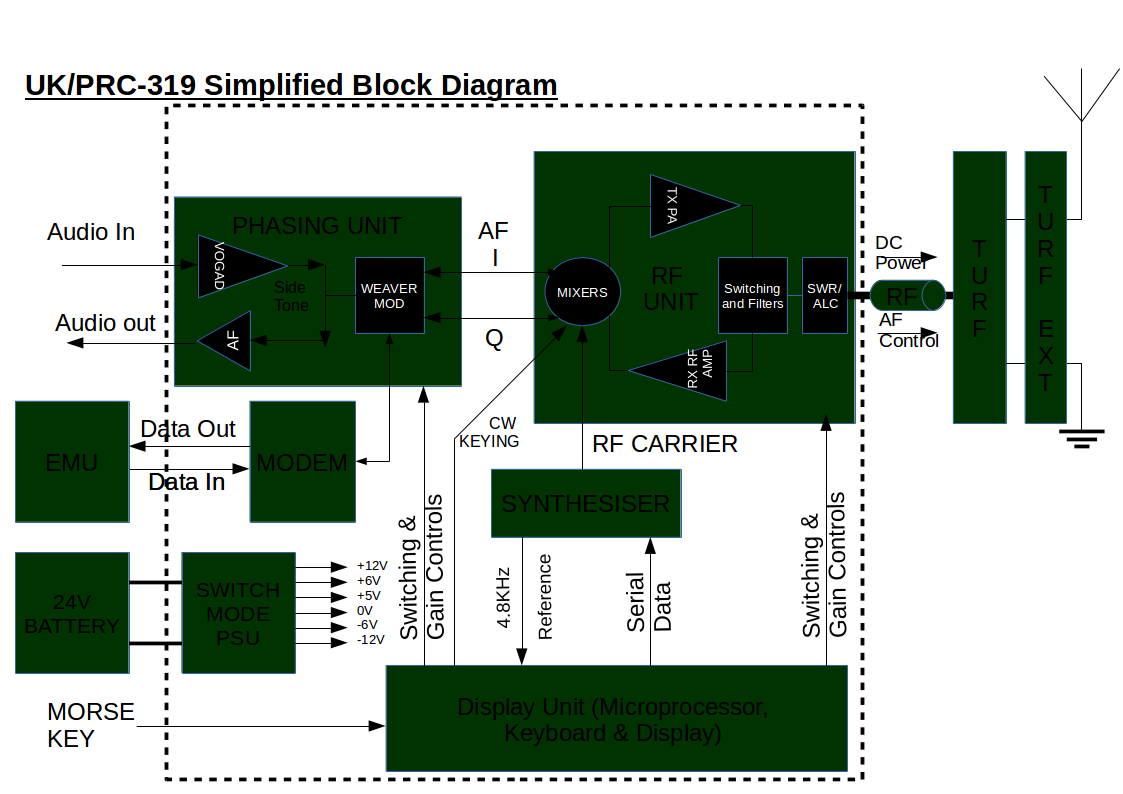
Technical Description
The set is a direct conversion set using audio phasing (Weaver's Method) to generate SSB. This avoids any RF emissions except wideband CPU noise and the intended carrier - there is no local oscillator or IF to leak. SSB is generated and both SSB and CW are demodulated at audio frequency and the synthesiser operates at the carrier frequency. The internal operation of the set is documented in the following block diagram:
(based on AESP 5820-F-303 at http://www.pa3ect.eu)
The radio has two standard Clansman 7-pin audio sockets (of which No. 2 can be used for data operation), a battery float charge connector (is apparently for a data terminal called DMHD), a mode control, a volume control and a power switch and a simple keypad. Frequency setting is via the keypad. The manual specifies for CW operation that the headset should be connected to socket 1 (top) and the key in socket 2 (bottom). The radio has 10 pairs of memories R0 to R9 for receive and T0 to T9 for transmit. Any combination of T and R memories can be used for the current frequency. If the TURF ATU is connected it can be tuned for both frequencies and will remember the settings. Frequencies are stored as 6 digits to 100Hz accuracy e.g. 071870 is 7.1870 MHz. Operating modes selectable via the mode switch are CW (the key uses the microphone PTT connections on the audio sockets), USB single sideband and data at 75, 150 or 300 baud AFSK. Note that the handset PTT is not operational in data mode.
LSB conversion is relatively easy - electrically it is only necessary to swap connections in the weaver 3rd method modulator. The challenge is to do it in a mechanically robust way and not introduce crosstalk or pick up electrical noise in the extra wires. The mod is described by PA3ECT. My radio was converted before I got it.
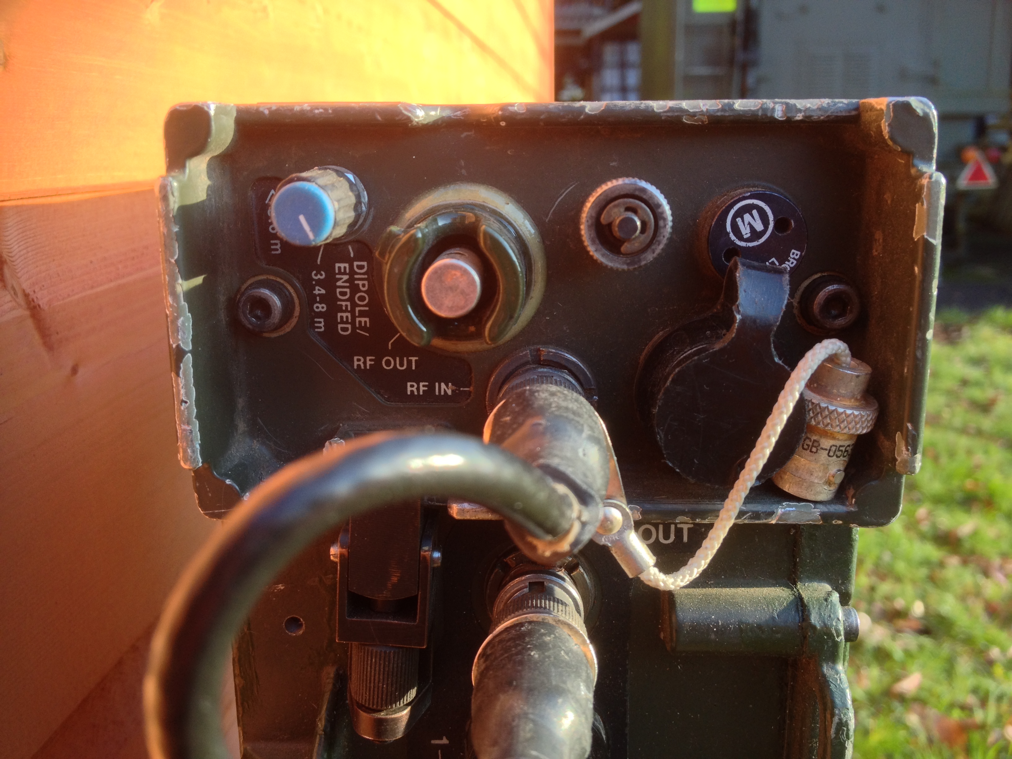
The TURF (automatic ATU) gets power and control messages over the RF coaxial cable allowing it to be easily remoted from the radio to the antenna feed point. It uses latching relays for minimum power consumption (and as an aside once tuned, can be used with other radios as long as they are AC coupled to protect the ATU). The TURF has an antenna switch with 3 switch positions based on antenna length:
- < 3.4M (used for whip)
- 3.4-8M - used for precut 5m and 7m wire antennas covering 4-23 and 3.4-17MHz
- DIPOLE/ENDFED - used for dipole (with coax feed adapter) or 1/4 wave or 3/4 wave wires
The TURF has binding posts for antenna and ground (or counterpoise wire). Dipoles can be connected to the TURF using an adapter from binding posts to a BNC socket. The TURF alone cannot match all end fed antennas below 3.5MHz. A separate TURF Extender box clamps on top of the TURF and provides additional switched inductors. The TURF extender is connected to the TURF by a short 7 pin to 7 pin cable. TURF tuning is claimed as 200ms for a new frequency or 35ms for a stored frequency with a target SWR of 1.5 to 1.
The internal modem is connected to a socket on the side of the EMU bay and operates at 75, 150 and 300 Baud selected by a front panel switch. The modem provides clock to the EMU. Messages are modulated using tones of 1575Hz for Mark and 2425Hz for Space (an 850Hz shift). The EMU supports a simple digital selective call system - stations are assigned 6 decimal digit callsigns and will receive messages addressed to their own callsign or address 000000 for broadcasts. The W0RW RWOP protocol is a mapping of the English alphabet and punctuation to 2-digit decimal supported by the numeric-only EMU for amateur radio use and runs on top of the STANAG 4202 air interface.
The bottom of the radio has power input studs for standard Clansman 24V batteries. Possible power sources are
- 4AH standard Ni-Cad pack
- 1AH Ni-Cad pack with Clansman hand charger
- 16AH single use Lithium Battery
- Any of the above connected via a battery extension cable
- Lead-Acid signals batteries connected via crocodile leads
The provided antenna is a 2.5m sectional whip similar to that for the UK/PRC-320 - unlike the UK/PRC-320 there is no provision for directly mounting it on the radio - a combined ground spike and screwdriver is provided and the radio is clearly transportable rather than pedestrian mobile in concept.
The radio is provided with built in self test facilities controlled by the microprocessor that can do basic tests of transmitter, receiver and modem. The EMU has its own self tests and the EMU transmitted signal is also audible to the operator via the headset.
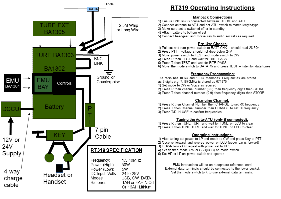
Short Form Instructions
I have prepared two A4 page cards that can conveniently be laminated back to back with instructions for the EMU and RT319 for field use. These can be downloaded full size by clicking on the images.
UK/PRC-319 Photos
Visit http://d3guoyyrmod405.cloudfront.net/clansman/RT319/ for full size versions of the photos in this page, and more.
I am grateful to Al G8LIT for the loan of his set which is featured in some of the older images.
UK/PRC-319 Recordings
Click on the links to download/listen or visit http://d3guoyyrmod405.cloudfront.net/videos/RT319/index.htm
UK/PRC-319 Links
[ Clansman Home ]
[ Radios ]
[ Antennas? ]
[ Audio? ]
[ Batteries? ]
[ Connectors? ]
[ Harness? ]
[ Other? ]
[ Links? ]